Page 17/37
Operating Instructions BA 373-E66
Technical specifications subject to change
W. Bälz & Sohn GmbH & Co. Koepffstrasse 5 74076 Heilbronn Germany
Phone +49 (0)7131 15 00 0 Fax +49 (0)7131 15 00 21 www.baelz.de mail@baelz.de
Observe copyright protection DIN 34
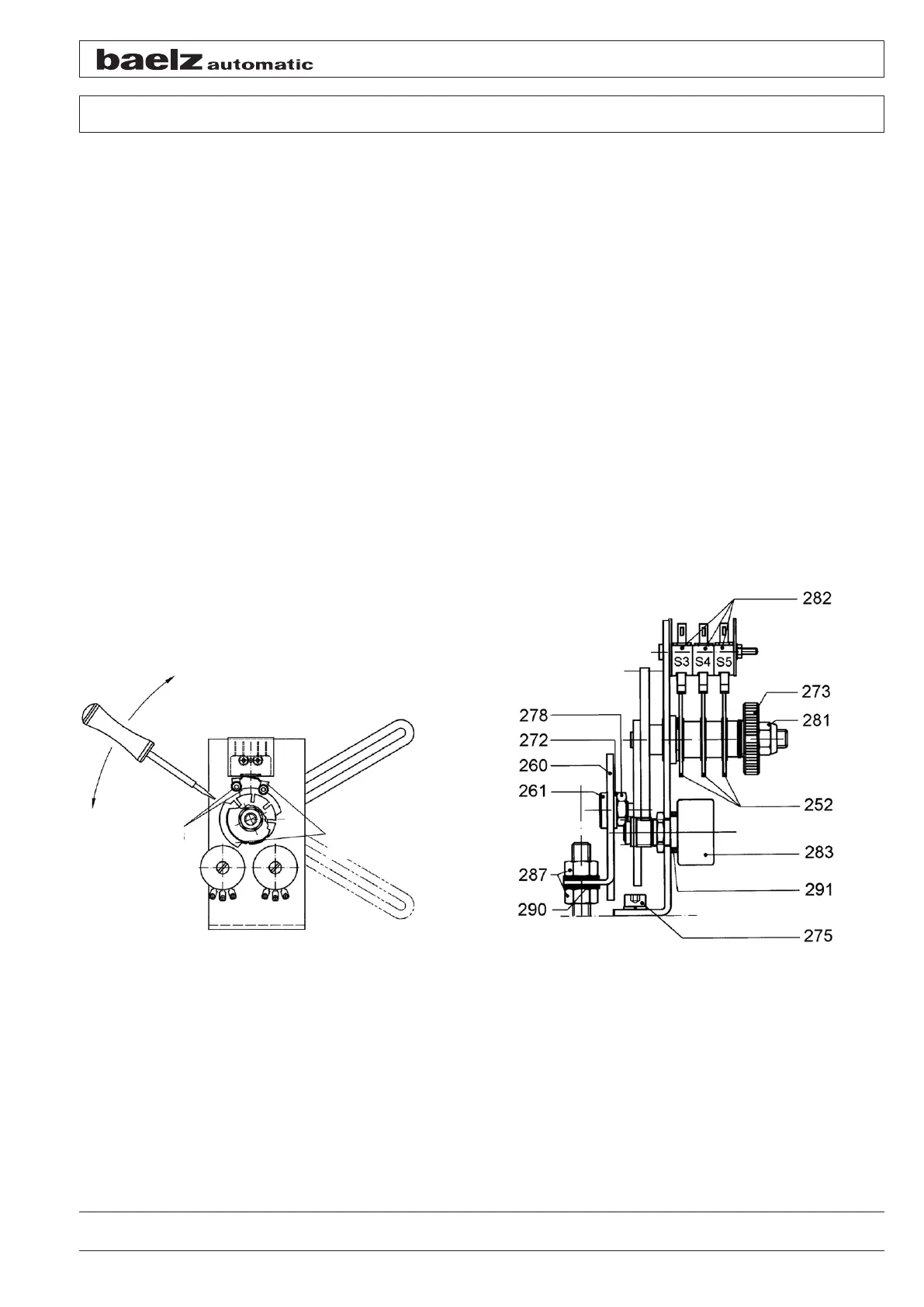
6.5 Setting the limit switches S3 and S4
● Retract the actuator connecting rod by the set travel
● Unscrew the knurled nut [273] up to the self-locking nut [281]
● Insert a screwdriver into one of the cam slots (of the cam set next to the mounting angle) for switch S3
[282]
● Rotate the cam until the switching roll of switch S3 is lifted by the cam and the switch switches; if necessary
use a measuring instrument to check the switching point
● Set the switching cam for switch S4 [282] for "extending connecting rod" or intermediate positions as re-
quired
● After completing the setting, retighten the knurled nut [273]
Do not change the position of the self-locking nut [281]. The switching cams cannot be turned easily. The use of
driving lever [259] to hold the gear wheel when turning the switching cams is recommended. It must generally be
ensured that WE switches S3 and S4 [282] can only be operated from the direction of the switching cams [252].
If necessary, the switching lever position can be changed after loosening the screw connection of the switches and
by opening the switches.
Figure 13: Cam setting Figure 14: Switching and signalling unit
Cam and
switch S3
and S4
Cam and
switch S5
open
closed