Page 20/37
Operating Instructions BA 373-E66
Technical specifications subject to change
W. Bälz & Sohn GmbH & Co. Koepffstrasse 5 74076 Heilbronn Germany
Phone +49 (0)7131 15 00 0 Fax +49 (0)7131 15 00 21 www.baelz.de mail@baelz.de
Observe copyright protection DIN 34
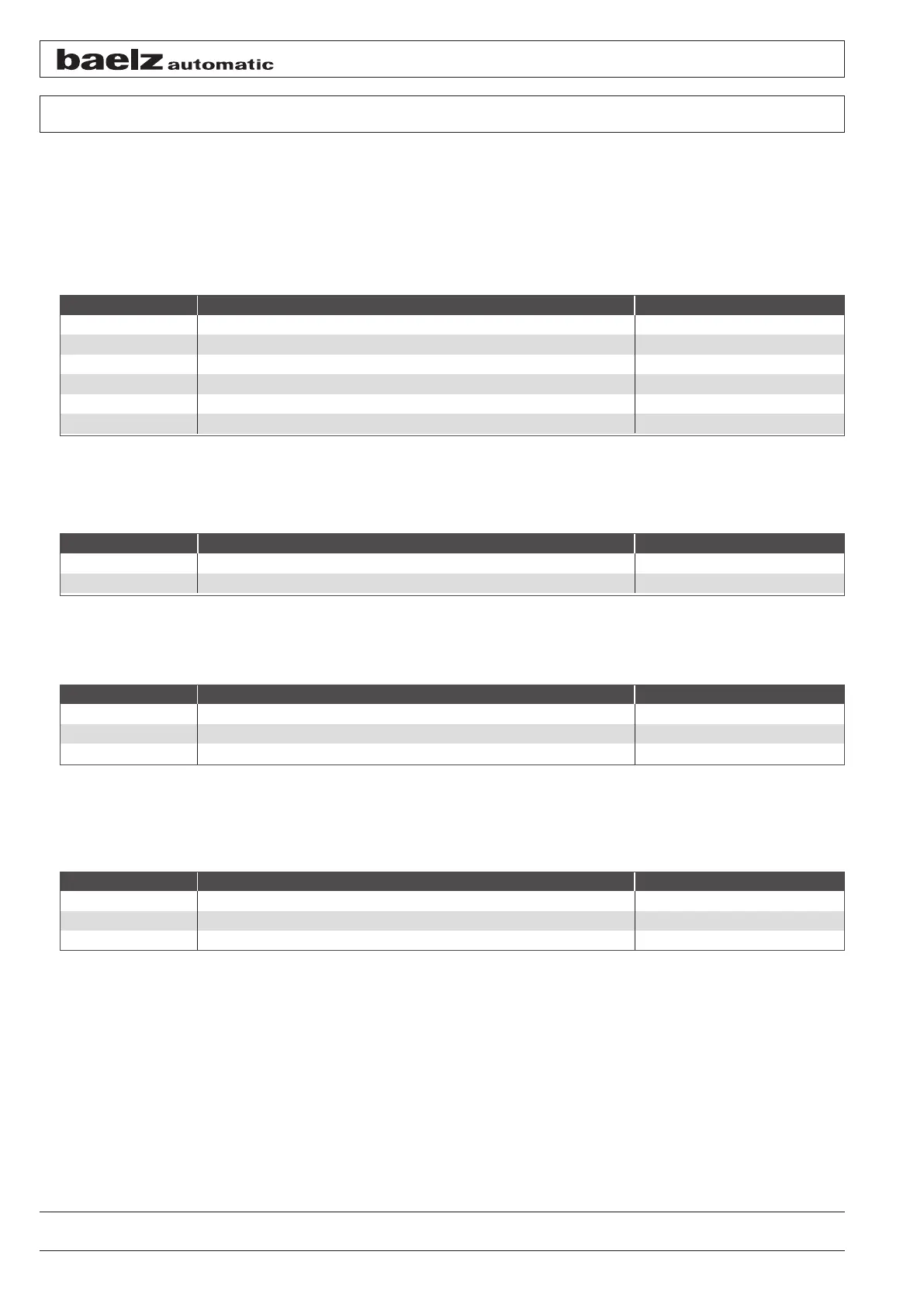
7.3.1 Terminal assignment
Terminal X4:
To avoid interference, route the signal lines separately from the voltage supply lines. Particularly when using volt-
age signals, we recommend to use a shielded cable and to connect the shield to the protective earth (PE) connec-
tion on the actuator housing.
The impedance of the current input is 50 Ω. When using the voltage input, the impedance is 20 kΩ.
Terminal X2:
Terminal X3:
Connector X4:
The potentiometer is plugged onto the positioner's printed circuit board using a connector.
Figure 16: Pin assignment table
Terminal Function
54 L Power input Phase 50/60 Hz
55 N Power input Neutral
Terminal Function
60 Output mA 0 (4)...20 mA
61 Output Volt 0 (2)...10 V
58 GND Ground
57 GND Ground
56 Input Volt 0 (2)...10 V
59 Intput mA 0 (4)...20 mA
Terminal Function
51 L↑ Phase, spindle retracts 50/60 Hz
52 N Neutral, power input
53 L↑ Phase, spindle extends 50/60 Hz
Pin Function
1 Maximum value blue
2 Sensing at the slider green
3 Zero red