www.balluff.com 9english
5.1 Assembling the amplifier
The following fitting methods are available:
– Simple clamp fitting on the hat rail acc. to DIN, 35mm
or 15mm
– Screw fixing with pan-head M3 screws
5.2 Connecting the amplifier
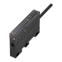
The amplifier can be operated with type BCS…-XXS-…
sensors.
Fig. 5-1: Connecting the sensor
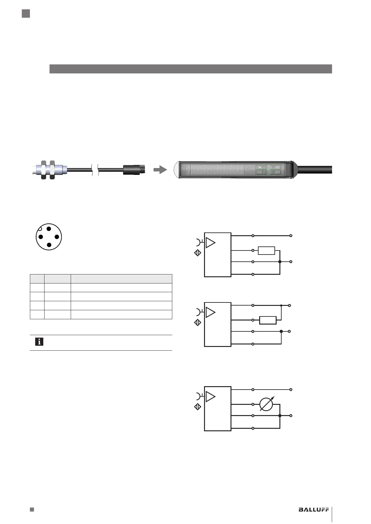
5.3 Electrical Connection
Fig. 5-2:
4
3
1
2
Plug layout (top view of M12 plug)
Pin Color Signal
1 BN U
e
+ (Operating voltage +)
2 WH Teach line
3 BU U
e
− (Operating voltage −)
4 BK Output signal
Tab. 5-1: Pin assignment
In normal operation, the white teach line must
always be connected to the blue negative line.
5
Installation and connection
5.4 Switching operation
Fig. 5-3:
BN
+
OUT
ext. prog.
–
3
+
–
BK
BU
WH
PNP
1
4
3
2
+
–
BN
3
BK
BU
WH
NPN
1
4
3
2
+
OUT
ext. prog.
–
Switching operation
5.5 Analog operation
Fig. 5-4:
BN
+
OUT
ext. prog.
–
3
+
–
BK
BU
WH
1
4
3
2
Analog operation
BAE SA-CS-026-YP-BP02 / BAE SA-CS-026-YP-BP00,3-GS04
Comfort Sensor Amplifier
 Loading...