Do you have a question about the Balluff BAE SA-CS-026-YP-BP02 and is the answer not in the manual?
Indicates the availability of the user manual in German.
Indicates the availability of the user guide in English.
Specifies the models and scope of this user guide.
Lists additional relevant documents available on the Balluff website.
Explains the symbols and conventions used for instructions and notes.
Details the structure and meaning of safety warning signals.
Defines technical terms and abbreviations used in the guide.
Describes the intended application of the comfort sensor amplifier.
Outlines applications and areas where the product must not be used.
Provides essential safety guidelines for installation, operation, and maintenance.
Lists the items included in the product delivery.
Provides guidelines for transporting the product to its location of use.
Specifies the conditions required for storing the product.
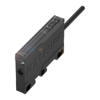
Illustrates and labels the physical components of the sensor amplifier.
Explains how the sensor amplifier operates and processes signals.
Details the function of each display element and button on the device.
Describes the available methods for physically mounting the amplifier.
Explains how to connect the amplifier to compatible sensors.
Provides pin assignments and wiring diagrams for electrical connections.
Details the wiring for PNP and NPN switching output configurations.
Details the wiring for analog output configurations.
Guides through the initial steps for powering up and checking the amplifier.
Provides a streamlined process for initial sensor adjustment and teaching.
Offers important considerations for ongoing operation and system integrity.
States the maintenance requirements for the product.
Explains how to navigate through the amplifier's menu structure using buttons.
Describes how to exit the operating mode and save settings.
Presents a detailed breakdown of the menu structure for switching and analog modes.
Explains the display of analog sensor values and their measurement range.
Covers teaching and manual adjustment of switchpoints.
Details selection of operating modes, amplifier types, and switching modes.
Step-by-step guides for teaching switch-on (SP1) and switch-off (SP2) points.
Explains setting switch-on/off delays and external triggers.
Covers configuration options related to the device display.
Describes closing the menu and returning to factory settings.
Lists possible error messages, their causes, and troubleshooting steps.
Provides information on who can perform repairs on the product.
Advises on how to properly dispose of the product according to regulations.
Specifies the operating and storage temperature ranges and protection rating.
Lists key electrical specifications like supply voltage, current, and frequency.
Details the connector type and conductor configuration for electrical connections.
Shows relevant certifications and marks for product compliance.
Detailed breakdown of the menu structure for switching mode operation.
Details parameters, buttons, and functions within the switching mode menu.
Detailed breakdown of the menu structure for analog mode operation.
Details parameters, buttons, and functions within the analog mode menu.
| Operating Voltage Ub | 10...30 VDC |
|---|---|
| Rated operating voltage Ue DC | 24 VDC |
| Short-circuit protection | Yes |
| Operating current Ie | 200 mA |
| No-load current Io max. at Ue | <= 15 mA |
| Switching frequency f max. | 500 Hz |
| Hysteresis H max. | 15% |
| Ambient temperature Ta | -25...70 °C |
| Protection class | IP67 |
| Sensing face material | PBT |
| Switching output | PNP |
| Connection | Connector, M12, 4-pin |
| Current Consumption | <= 15 mA |
| Operating Temperature | -25...70 °C |
| Weight | 50 g |
| Storage Temperature | -40...85 °C |