www.balluff.com 21english
11
Appendix
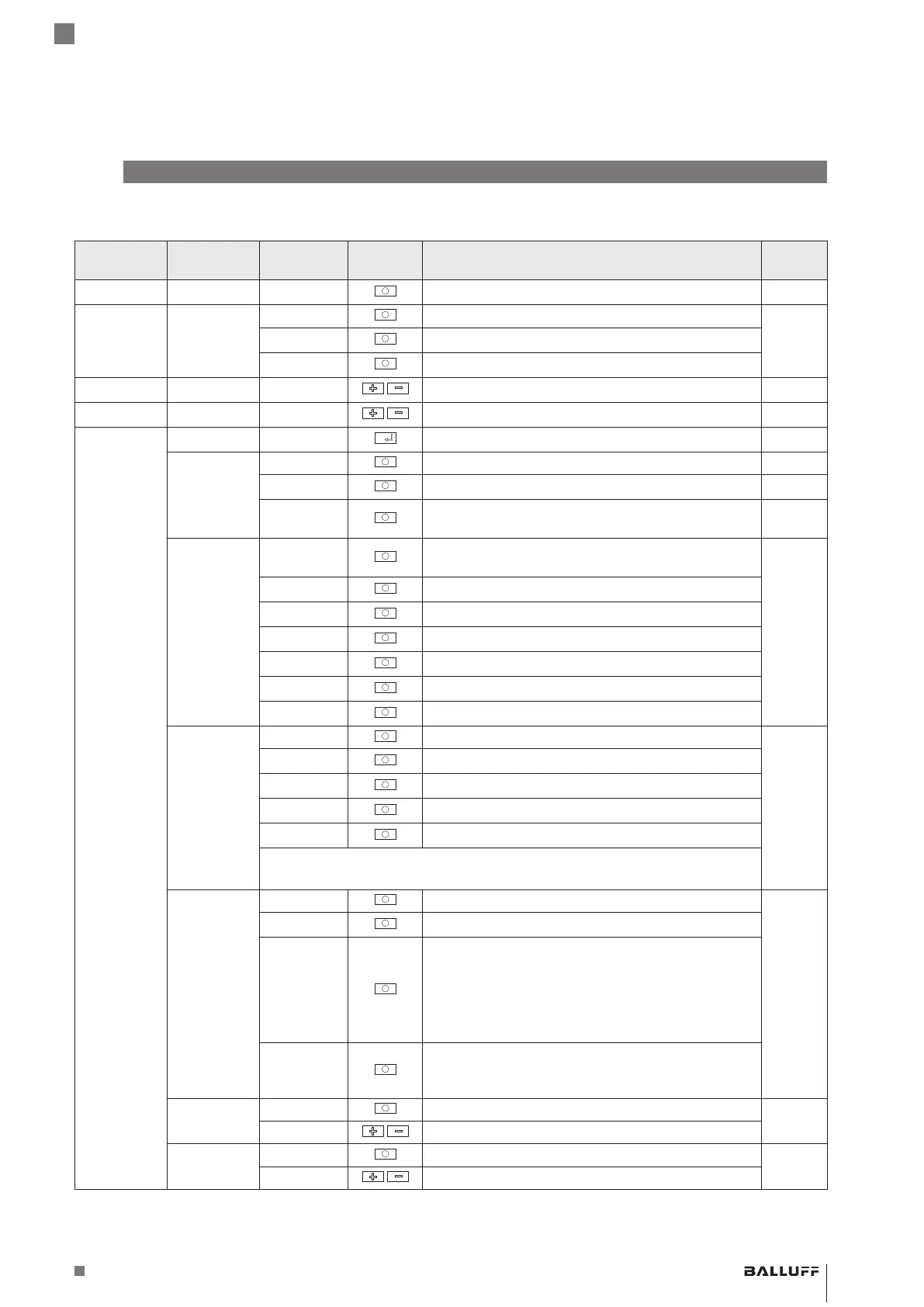
11.1 Switching operating mode menu structure
Main menu
(1st level)
Submenu
(2nd level)
Parameter Button(s) Function Section
1
i n
Analog sensor value (in digits) 7.2
2
t S
Teaching in switchpoints 7.3.1
SP 1
Teach in switchpoint1
SP2
Teach in switchpoint2
3
SP 1
Manually adjusting switchpoint 1 7.4
4
SP2
Manually adjusting switchpoint 2 7.5
5
[
] c onf
Submenu: Configuration 7.6
a
SoA
Adjusting the operating mode (switching – analog) 7.6.1
S
Switching (this overview applies)
A
Analog output (see section11.2 Menu structure:
analog mode)
b
out
Adjusting the switching power amplifier type/analog
output
7.6.2
P no
PNP N.O.
n no
NPN N.O.
PP no
Push-pull, actuated = high side
P nc
PNP N.C.
n nc
NPN N.C.
PP nc
Push-pull, actuated = low side
c
Mod
Adjusting the switching mode 7.6.3
St d
Standard switching mode
2Pt
2-point switching
Wi n
Window function
dyn
Dynamic operation
After selecting the switching mode: return to the main menu
tS
to adjust
switchpoints.
d
E t t
Setting external triggers 7.6.4
oF F
Teach line inactive
t E A
Teach line active:
– SP1 (teach in switch-on point): briefly connect the
teach line (white) to U
B+
(brown)
– SP2 (teach in switch-off point): briefly connect the
teach line (white) to U
B–
(blue)
Applies for switching modes Std, 2Pt, and Win.
PuMP
E.g. fill level regulation with 2 sensors and amplifiers.
System1 reports minimum fill level to system2 via
control line.
e
don
Setting the switch-on delay 7.6.5
Switch-on delay input (0…6500×10ms)
f
dof
Setting the switch-off delay 7.6.6
Switch-off delay input (0…6500×10ms)
BAE SA-CS-026-YP-BP02 / BAE SA-CS-026-YP-BP00,3-GS04
Comfort Sensor Amplifier
 Loading...