Do you have a question about the Balluff BNI ECT-508-105-Z015 and is the answer not in the manual?
The communication between the BNI ECT-508-105-2015 and the controlling system is done via the EtherCAT.
In the project administration, the Bus module BNI ECT-508-105-2015 is depicted as a modular device.
For example, the connection of the BNI ECT-508-105-2015 to a Beckhoff TwinCAT controller is shown with the TwinCAT System Manager.
Bit mapping and function of the configurable modules. Signal from configured inputs or outputs are depicted.
The BNI ECT-... is a decentralized IO-Link input and output module for connecting to the EtherCAT ™ network.
Installation and startup are to be performed only by trained specialists. Qualified personnel are persons who are familiar with the installation and operation of the product.
Before commissioning, carefully read the operating manual. The system must not be used in applications in which the safety of persons is dependent on the function of the device.
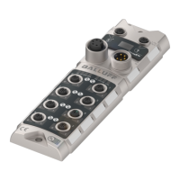
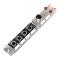
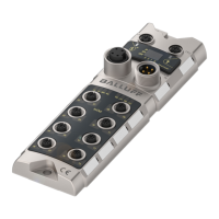
Overview of the BNI ECT-508-105-2015 module, showing numbered components and their function.
Details the electrical connections for Power supply, Grounding, and EtherCAT interface.
Details Ethernet port type, connection, cable types, data transmission rate, cable length, and flow control.
Explains the meaning of module status and port/pin LEDs, detailing their display and function.
Details IO-Link service data, including control, status, index, subindex, length, data, and error code.
Details IO-Link configuration data, including device ID, vendor ID, product ID, serial number, revision, and master control.
Introduces the integrated web server for detailed information and configuration of connected IO-Link devices.
Explains that EoE must be configured first to access the module's web server.
Explains the necessity of logging in for configuration access and the default password.
Permits configuration of module information texts and parameters, with options to save, reboot, or factory reset.
Displays internal module diagnostics, events, and provides a tool for detailed troubleshooting.
| Brand | Balluff |
|---|---|
| Model | BNI ECT-508-105-Z015 |
| Category | Control Unit |
| Language | English |