Do you have a question about the Balluff BNI PNT-502-102-Z015 and is the answer not in the manual?
Explains how the manual is organized chapter by chapter, with content building upon previous sections.
Details symbols, actions, syntax, and cross-references used throughout the manual for clarity.
Lists key symbols and abbreviations used in the document to ensure consistent understanding.
Notes that product illustrations and views in the manual may differ from the actual product.
Outlines the proper intended use of the module and procedures for safe installation and startup.
Provides essential safety guidelines for commissioning, operation, and handling of the device.
Covers resistance to aggressive substances and precautions for hazardous voltage.
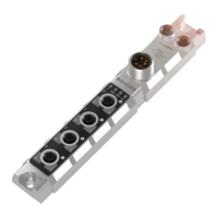
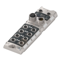
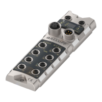
Presents a visual overview of the BNI PNT module, labeling all key components and ports.
Details the mechanical aspects of connecting the module, including mounting.
Explains the electrical connections for power supply and grounding.
Describes the PROFINET interface connection and pin assignment.
Details the configuration and pin assignment for the standard I/O port.
Explains the IO-Link port functionality and pin assignments.
Provides a summary of port designations and their functions.
Provides detailed physical dimensions of the module with a diagram.
Specifies mechanical properties such as housing material and installation type.
Defines the operating temperature and storage temperature ranges.
Lists electrical specifications including supply voltage and ripple.
Details PROFINET port specifications, data rates, and cable types.
Explains the meaning of module status LEDs and port LEDs.
Describes the status indicators for standard and IO-Link ports.
Covers project planning using GSDML files and module integration into networks.
Details how to configure port functions and diagnostic functions in the header module.
Guides on configuring modules, addressing, and mapping IO-Link or standard I/O.
Explains how to configure IO-Link parameters for respective port pins.
Covers viewing and configuring the device name and Profinet address.
Explains how to establish a device relationship and assign a device name.
Details the process of assigning a device name using network tools.
Describes final steps and troubleshooting for completing module configuration.
Defines module settings, port functions, and safe state configurations.
Details the bit mapping for inputs, outputs, and various diagnostic functions.
Explains how to switch IO-Link diagnostics on or off for ports.
Explains IO-Link communication speed, data selection, and validation settings.
Describes settings for data management, parameter storage, and identification.
Introduces the module's LCD display, LEDs, and buttons for interaction.
Explains the use of arrow keys and set keys for navigating and modifying settings.
Details displayed information like IP addresses, device names, and firmware versions.
Illustrates display functions and navigation using symbols and flowcharts.
Guides through the initial startup sequence and main menu navigation.
Covers procedures for factory reset and viewing module information.
Introduces the integrated web server for retrieving device information and configuration.
Explains the web interface navigation bar and the content of the 'Info' tab.
Details the process for logging into and out of the web interface for configuration access.
Describes the 'Home' page displaying essential module and network status information.
Shows how to view IO-Link device data and parameters via the 'Ports' dialog.
Explains transferring IODD files for detailed device representation in the 'Ports' dialog.
Covers module and port configuration settings via the web interface's 'Config' dialog.
Provides access to device logs and event history for detailed troubleshooting.
Details the 34-byte diagnostics message format, divided into blocks like Header and Alarm Specifier.
Explains the components of the Block Header, including Block Type, Length, and Version.
Describes the Alarm Specifier fields, covering sequence number and diagnostic status.
Identifies where errors occur on the module or IO-Link devices by channel number.
Defines channel properties such as type, maintenance status, and direction.
Lists specific error codes and their corresponding descriptions for troubleshooting.
Outlines methods for configuring IO-Link devices via web server, function modules, or tools.
Explains how to read and write data from IO-Link devices using telegrams and tasks.
Lists all components included in the BNI PNT module package.
Provides product ordering codes and related information for the Balluff network interface.
Explains how the manual is organized chapter by chapter, with content building upon previous sections.
Details symbols, actions, syntax, and cross-references used throughout the manual for clarity.
Lists key symbols and abbreviations used in the document to ensure consistent understanding.
Notes that product illustrations and views in the manual may differ from the actual product.
Outlines the proper intended use of the module and procedures for safe installation and startup.
Provides essential safety guidelines for commissioning, operation, and handling of the device.
Covers resistance to aggressive substances and precautions for hazardous voltage.
Presents a visual overview of the BNI PNT module, labeling all key components and ports.
Details the mechanical aspects of connecting the module, including mounting.
Explains the electrical connections for power supply and grounding.
Describes the PROFINET interface connection and pin assignment.
Details the configuration and pin assignment for the standard I/O port.
Explains the IO-Link port functionality and pin assignments.
Provides a summary of port designations and their functions.
Provides detailed physical dimensions of the module with a diagram.
Specifies mechanical properties such as housing material and installation type.
Defines the operating temperature and storage temperature ranges.
Lists electrical specifications including supply voltage and ripple.
Details PROFINET port specifications, data rates, and cable types.
Explains the meaning of module status LEDs and port LEDs.
Describes the status indicators for standard and IO-Link ports.
Covers project planning using GSDML files and module integration into networks.
Details how to configure port functions and diagnostic functions in the header module.
Guides on configuring modules, addressing, and mapping IO-Link or standard I/O.
Explains how to configure IO-Link parameters for respective port pins.
Covers viewing and configuring the device name and Profinet address.
Explains how to establish a device relationship and assign a device name.
Details the process of assigning a device name using network tools.
Describes final steps and troubleshooting for completing module configuration.
Defines module settings, port functions, and safe state configurations.
Details the bit mapping for inputs, outputs, and various diagnostic functions.
Explains how to switch IO-Link diagnostics on or off for ports.
Explains IO-Link communication speed, data selection, and validation settings.
Describes settings for data management, parameter storage, and identification.
Introduces the module's LCD display, LEDs, and buttons for interaction.
Explains the use of arrow keys and set keys for navigating and modifying settings.
Details displayed information like IP addresses, device names, and firmware versions.
Illustrates display functions and navigation using symbols and flowcharts.
Guides through the initial startup sequence and main menu navigation.
Covers procedures for factory reset and viewing module information.
Introduces the integrated web server for retrieving device information and configuration.
Explains the web interface navigation bar and the content of the 'Info' tab.
Details the process for logging into and out of the web interface for configuration access.
Describes the 'Home' page displaying essential module and network status information.
Shows how to view IO-Link device data and parameters via the 'Ports' dialog.
Explains transferring IODD files for detailed device representation in the 'Ports' dialog.
Covers module and port configuration settings via the web interface's 'Config' dialog.
Provides access to device logs and event history for detailed troubleshooting.
Details the 34-byte diagnostics message format, divided into blocks like Header and Alarm Specifier.
Explains the components of the Block Header, including Block Type, Length, and Version.
Describes the Alarm Specifier fields, covering sequence number and diagnostic status.
Identifies where errors occur on the module or IO-Link devices by channel number.
Defines channel properties such as type, maintenance status, and direction.
Lists specific error codes and their corresponding descriptions for troubleshooting.
Outlines methods for configuring IO-Link devices via web server, function modules, or tools.
Explains how to read and write data from IO-Link devices using telegrams and tasks.
Lists all components included in the BNI PNT module package.
Provides product ordering codes and related information for the Balluff network interface.
| Model | BNI PNT-502-102-Z015 |
|---|---|
| Supply Voltage | 24 V DC |
| Rated operating voltage Ue DC | 24 V DC |
| Ripple max. | 10 % |
| Voltage drop Ud max. | 2 V |
| Network cycle time min. | 1 ms |
| Process data cycle min. | 1 ms |
| Number of digital inputs | 8 |
| Input current per channel | 3 mA |
| Number of digital outputs | 8 |
| Output current per channel, max. | 500 mA |
| Output voltage | 24 V DC |
| Short circuit protected | Yes |
| Overload protected | Yes |
| Protection type per EN 60529 | IP67 |
| Approval/Conformity | CE, UL |
| Interface | PROFINET |
| Number of Ports | 2 |
| Protection Class | III |
| Input voltage high | >= 15 V |
| Input voltage low | <= 5 V |
| Output delay, ON to OFF max. | 1 ms |
| Storage temperature | -25 to 70 °C |
| Connection | M12 |
| Connection Type | Plug |