Do you have a question about the Balluff Micropulse BTL5 Series and is the answer not in the manual?
Defines the document's coverage of installation and technical data for the EX linear position sensor.
Advises users to install and use the sensor according to design, forbidding modifications to prevent damage or injury.
Emphasizes following safety regulations for sensor use and inspection to prevent hazards.
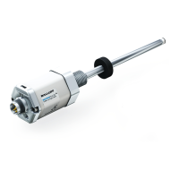
Explains the sensor's purpose for accurate position feedback in explosive atmospheres.
Provides detailed physical dimensions and mounting information for the sensor.
Lists technical specifications including measuring range, materials, temperature, and environmental protection.
Details available magnet types for use with the sensor, including order codes and materials.
Describes the conduit adapter accessory, its material, and ATEX approvals.
Presents approved float magnets for liquid-level applications, with specifications and limitations.
Step-by-step guide for installing the linear position sensor, including warnings and torque specifications.
Provides instructions for preparing cylinder ports for sensor installation according to specific diagrams.
Specifies requirements for installing the sensor rod in Zone 0 areas, adhering to safety regulations.
Details pin assignments and connection diagrams for various output types like Analog, SSI, Profibus, and CANbus.
Explains how to use the optional analog programming tool to scale the electrical stroke length.
Provides a procedure for safely replacing the electronics module to maintain product certification.
| Protection Class | IP67 |
|---|---|
| Type | Micropulse |
| Resolution | 1 µm |
| Output Signal | Analog, SSI |
| Series | Micropulse BTL5 |