www.balluff.com • 1-800-543-8390
13
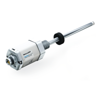
BTL5-_-M_-J-DEXC-TA12
Micropulse Linear Position Sensor
Analog & Digital-Pulse Outputs
Explosion-Proof Rod Style
Zone 1
Dividing Area
Zone 0
6.3 Installing in Locations Classified as Zone 0 Under ATEX and IECEx Guidelines
Only the rod section of the linear position sensor may extend into Zone 0. To ensure
safe isolation between Zone 0 and Zone 1, the relevant safety regulations detailed
in IEC/EN60079-26 must be strictly adhered to. The linear position sensor must be
installed in a manner that will result in a sufficiently tight joint (IP67) or flameproof
joint (IEC/EN60079-1) between the less hazardous area and Zone 0.
When using a float magnet, it is necessary that a static discharge
between the linear position sensor rod and the inner portion
of the float be prevented. The floats listed in the accessory
section (5.2) are designed so that, in normal operation, the float
is tilted, thereby ensuring mechanical contact between the linear
position sensor rod and the float wall. Do not use other types of floats
or attempt to disable this design feature.
Note: The linear position sensor is not approved for use in locations classified
as Zone 0 under North American guidelines.
87654321
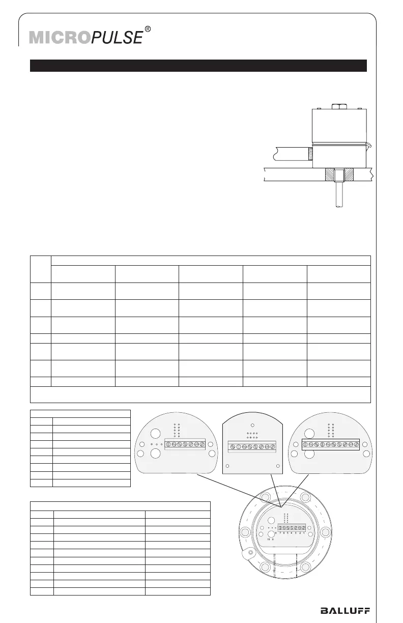
Output Type (Order Code) Fig. 2
Pin Profibus (T)
1 RxD/TxD-N
2 RxD/TxD-P
3 Data GND
4 Pwr Supply GND
5 Pwr Supply (+)
6 VP (+5V Output)
7 Not used
8 Not used
Output Type (Order Code) Fig. 3
Pin Quadrature (Q) CANbus (H)
1 Output Channel A (+) CAN GND
2 Output Channel B (+) CAN Low
3 Output Channel A (-) CAN High
4 Pwr Supply GND Pwr Supply GND
5 Pwr Supply (+10 to +30 Vdc) Pwr Supply (+24V)
6 Output Channel B (-) CAN GND
7 Output Channel Z (+) CAN Low
8 Output Channel Z (-) CAN High
9 Strobe Input Not used
10 Not used Not used
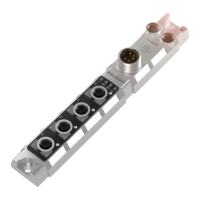
Typical housing with
terminal block assembly.
87654321
10 9
87654321
10 9
87654321
87654321
10 9
6.4 Wiring
Fig. 1 Fig. 2 Fig. 3
Pin Output Type (Order Code) Fig. 1
Analog Voltage
(A/B/G)
Analog Current
(C/E)
Digital START/
STOP (I/K/M/N/P)
Digital PWM
(L/R)
SSI
(S)
1 not used Signal Out Interrogate (+)
(input)
Interrogate (+)
(input)
CLK (+)
(input)
2 signal GND Signal GND START/STOP (+)
(output)
GATE (+)
(output)
DATA (+)
(output)
3 Signal Out (failing) not used Interrogate (-)
1
(input)
Interrogate (-)
(input)
CLK (-)
(input)
4 Pwr Supply GND Pwr Supply GND Pwr Supply GND Pwr Supply GND Pwr Supply GND
5 Pwr Supply
(+10 to +30 vdc)
Pwr Supply
(+10 to +30 vdc)
Pwr Supply
(+10 to +30 vdc)
Pwr Supply
(+10 to +30 vdc)
Pwr Supply
6 Signal Out (rising) not used START/STOP (-)
1
(output)
GATE (-)
(output)
DATA (-)
(output)
7 not used not used not used not used not used
Note 1: Order code version "N" is a single-ended, TTL compatible START/STOP version. This version does not use
Interrogate (-) or START/STOP (-). Pins 3 and 6 should be left unconnected for "N" type linear position sensors.

 Loading...