1-800-543-8390 • www.balluff.com
2
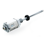
BTL5-_-M_-J-DEXC-TA12
Micropulse Linear Position Sensor
Analog & Digital-Pulse Outputs
Explosion-Proof Rod Style
The CE Mark verifies that our
products meet the requirements of
the current EMC Directive.
In our accredited EMC Laboratory, proof has
been documented that these Balluff products
meet the EMC requirements of the following
product standard:
EN 61326-2-3
(noise immunity and emission)
Emission tests:
RF Emission
EN 55011
Noise immunity tests:
Static electricity (ESD)
EN 61000-4-2 Severity level 3
Electromagnetic fields (RFI)
EN 61000-4-3 Severity level 3
Fast transients (Burst)
EN 61000-4-4 Severity level 3
Surge
EN 61000-4-5 Severity level 2
Line-induced noise induced by high-
frequency fields
EN 61000-4-6 Severity level 3
Magnetic fields
EN 61000-4-8 Severity level 4
i Preface - ATEX Directive Instructions ......................................................................... 3-4
1 Introduction ..................................................................................................................... 4
1.1 Scope ............................................................................................................................... 4
1.2 Safety Advisory ................................................................................................................. 4
1.3 Approvals .......................................................................................................................... 5
2 General Information ........................................................................................................ 5
2.1 Functional Description ....................................................................................................... 5
3 Component Overview ..................................................................................................6-7
4 Mechanical Data ............................................................................................................. 8
4.1 Dimensions ....................................................................................................................... 8
4.2 Specifications.................................................................................................................... 9
5 Accessories ................................................................................................................... 10
5.1 Magnets.......................................................................................................................... 10
5.2 Conduit Adapter ............................................................................................................. 10
5.3 Floats .............................................................................................................................. 11
6 Installation Instructions ................................................................................................ 12
6.1 Installation Procedure (mounting bolt
specifications, tightening torque, etc.) ............................................................................. 12
6.2 Installation in Hydraulic/Pneumatic Cylinders .................................................................. 12
6.3 Installing in Zone 0 Locations .......................................................................................... 13
6.4 Wiring ............................................................................................................................. 13
6.5 Using Analog Programming Tool ..................................................................................... 14
6.6 Replacing Electronics Module ........................................................................................ 14
7 Order Code .................................................................................................................... 15
Contents

 Loading...