Do you have a question about the Balluff BNI006A and is the answer not in the manual?
Details where the software module AOI_BNI004A_40_27_041.L5X can be downloaded.
Specifies the Balluff EtherNet/IP Connectivity block version used for module development.
Lists the validated system components and hardware for developing the software module.
Outlines the three-step sequential process for installing and using the AOI module.
Details the hardware configuration steps, including Balluff EtherNet/IP IO-Link Master features.
Guides the user through importing the Add-On Instruction (AOI) module into the RSLogix5000 project.
Explains how to use the imported AOI module as a ladder instruction in RSLogix5000.
Explains the role of the User-Defined Data Type in defining the AOI interface for the project.
Details the main UDT and its sub-UDTs (Input, Output, Configuration) for data integration.
Describes the Input UDT, listing members and explaining discrete input data bits and status indicators.
Explains the Output UDT, detailing members and their functions for discrete output data bits and display controls.
Details the Configuration UDT, covering IO-Link data, port functions, validation types, and device identification.
Describes the IO_Link_Port_Data UDT for input and output data buffers allocated to each port.
Confirms module integration and outlines verifying AOI operation with tags and real devices.
Guides on validating input tag transitions by monitoring controller-scoped tags and physical inputs.
Demonstrates validating output tag transitions by monitoring controller-scoped tags and physical outputs.
Guides validation of configuration tags, focusing on AOI value correspondence and IO-Link mode settings.
Informs about the validation report according to Balluff QF 4.4.12 and how to obtain it.
Advises checking hardware layout and software configurations to ensure they match guide specifications.
Suggests observing raw EtherNet/IP master data in RSLogix5000 to diagnose issues.
Provides steps to validate software configuration, including communication checks and conflict resolution.
Recommends validating hardware by isolating components and checking network connections for issues.
Defines the Controller Organizer as the RSLogix5000 area for accessing project components like tags and modules.
Defines AOI as a reusable RSLogix5000 software module using UDTs and logic for control algorithms.
Defines a controller-scoped tag as a project-wide tag available to all programs for uniform use.
Defines an AOI Parameter as a tag specific to an AOI, limited to its discrete use within the function.
Defines UDT as a reusable module defining input/output tag names for AOI implementation.
Defines the I/O Configuration Tree as the RSLogix5000 area for defining physical inputs and outputs.
Defines EDS (Electronic Data Sheet) as a configuration file for hardware communication via EtherNet/IP.
Lists Balluff documents supporting the guide and module, obtainable via technical support contact.
Mentions user guides for connected IO-Link devices and AOI modules, downloadable from Balluff's website.
This document describes the installation, use, and maintenance of the Add-On Instruction (AOI) software module for the BNI EIP-502-105-Z015, a Balluff EtherNet/IP IO-Link Master. This software module is designed for use with RSLogix5000, specifically version 18.01 or later, and was validated using a Rockwell 1756-L63 controller. The corresponding hardware, the Balluff EtherNet/IP Connectivity block BNI EIP-508-105-Z015, has hardware version 5.0 and firmware version 3.1.
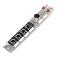
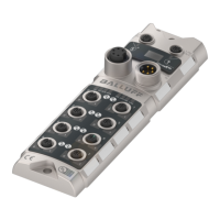
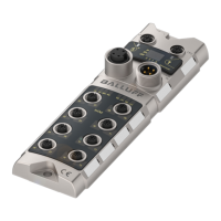
The BNI EIP-502-105-Z015 is an EtherNet/IP IO-Link Master device, designed to facilitate communication between a programmable logic controller (PLC) and various IO-Link devices. It features an embedded Ethernet switch, dual auxiliary power ports, and eight IO-Link ports. Each IO-Link port is highly configurable, supporting both IO-Link communication and standard input/output (I/O) functions. The device also includes a display menu for local configuration and status monitoring.
The Add-On Instruction (AOI) software module simplifies the integration of this IO-Link Master into RSLogix5000 projects. It provides a structured interface for accessing and controlling the master's functionalities, including input data, output data, and configuration parameters, without requiring manual mapping of individual data points. The AOI automates the parsing of data for each port, allowing the user to directly access data without dealing with the master's single data buffer.
The AOI utilizes several UDTs to define its interface and manage data:
UDT_BNI006A_Inputs_50_31_040 (12 bytes)
Data (INT): 16-bit register for discrete input data bits.Short_Circuit (INT): 16-bit register for discrete short circuit bits (between pins 1 and 3).Overload (INT): 16-bit register for discrete overload bits (functions if port is configured as output).UA_Fault (BOOL): Indicates auxiliary power status (e.g., Emergency Stop).US_Fault (BOOL): Indicates sensor power status.Port_x_IO_Link_Status (BOOL): Indicates if Port x (1-4) is in IO-Link mode.Port_x_Device_Connected (BOOL): Indicates if an operational IO-Link device is connected to Port x (1-4).Port_x_Validation_Failed (BOOL): Indicates if Port x (1-4) passed validation type.UDT_BNI004A_Outputs_40_27_041 (8 bytes)
Data (INT): 16-bit register for discrete output data bits.Restart (INT): 16-bit register for discrete Restart bits (toggled after short-circuit).Display_RED (BOOL): Transitions Red LED display on the BNI004A block.Display_GREEN (BOOL): Transitions Green LED display on the BNI004A block.Display_LOCK (BOOL): Locks the display, preventing user/PLC changes.UDT_BNI004A_Configuration_40_27_041 (204 bytes)
Port_x_Function (SINT): Determines port function (Standard I/O = 0, IO-Link = 1). Power cycle required for changes to take effect. Values 2 or higher result in Fallback mode.Port_x_Cycle_Time (SINT): Holds cycle time for Port x (bits 0-6 for value, bits 7-8 for time base).Port_x_Validation_Type (SINT): Defines validation type for Port x (0 = no validation, 1 = compatible device, 2 = exact device).Port_x_Vendor_ID (SINT): Vendor ID of the connected device (0378hex for Balluff devices).Port_x_Device_ID (SINT): Device ID of the connected device.Port_x_Serial_Number (SINT[16]): 16-byte SINT array for the serial number of the connected device.Port_x_Parameter_Upload_Enable (BOOL): Enables upload of current parameter set.Port_x_Parameter_Download_Enable (BOOL): Enables download of current parameter set.Port_x_Parameter_Server_Enable (BOOL): Enables upload or download of current parameter set.IO_Link_Port_Data (96 bytes)
Inputs (SINT[48]): 48-byte SINT array for raw input data from IO-Link slave to master.Outputs (SINT[48]): 48-byte SINT array for raw output data from IO-Link slave to master.Hardware Configuration:
Balluff_IO_Link_Master_BK40 (example)AOI Import:
AOI_BNI006A_50_31_040.L5X file. This will also import all associated UDTs.Ladder Logic Integration:
Master_Control_Tag for the AOI, Module_Name.I.Data for raw input data, Module_Name.O.Data for raw output data, Module_Name.C.Data for raw configuration data, and PortX_Data for IO-Link port data.Mapped_BNI_EIP_508_Data parameter, an instance of UDT_BNI006A_50_31_040, provides a consolidated view of all unique data associated with the BNI EIP-508 module.Configuration of IO-Link Ports:
Port_x_Function tag to 1 (Hex: 16#01).Port_x_Function values, power must be cycled to the BNI004A block for the changes to take effect.Port_x_Cycle_Time, Port_x_Validation_Type, Port_x_Vendor_ID, Port_x_Device_ID, and Port_x_Serial_Number as needed for connected IO-Link devices.Port_x_Parameter_Upload_Enable, Port_x_Parameter_Download_Enable, and Port_x_Parameter_Server_Enable (if supported by the IO-Link device).Troubleshooting:
IO_Link_Port_Data tag and the master's input buffer. For example, an input on Port 6, Pin 4 (Input buffer byte 0, bit 6) should be reflected in Mapped_Master_Data.I.Data.12 and in the master's raw input data (e.g., byte 8, bit 6 for Port 1).Documentation:
This comprehensive approach ensures proper installation, configuration, and troubleshooting of the Balluff BNI EIP-502-105-Z015 IO-Link Master using its dedicated AOI software module in RSLogix5000 environments.
| Brand | Balluff |
|---|---|
| Model | BNI006A |
| Category | Control Unit |
| Language | English |