(800) 543-8390 FAX (859) 727-8506 www.balluff.com
AOI_BNI006A_50_31_040 User Guide Page 12 of 26
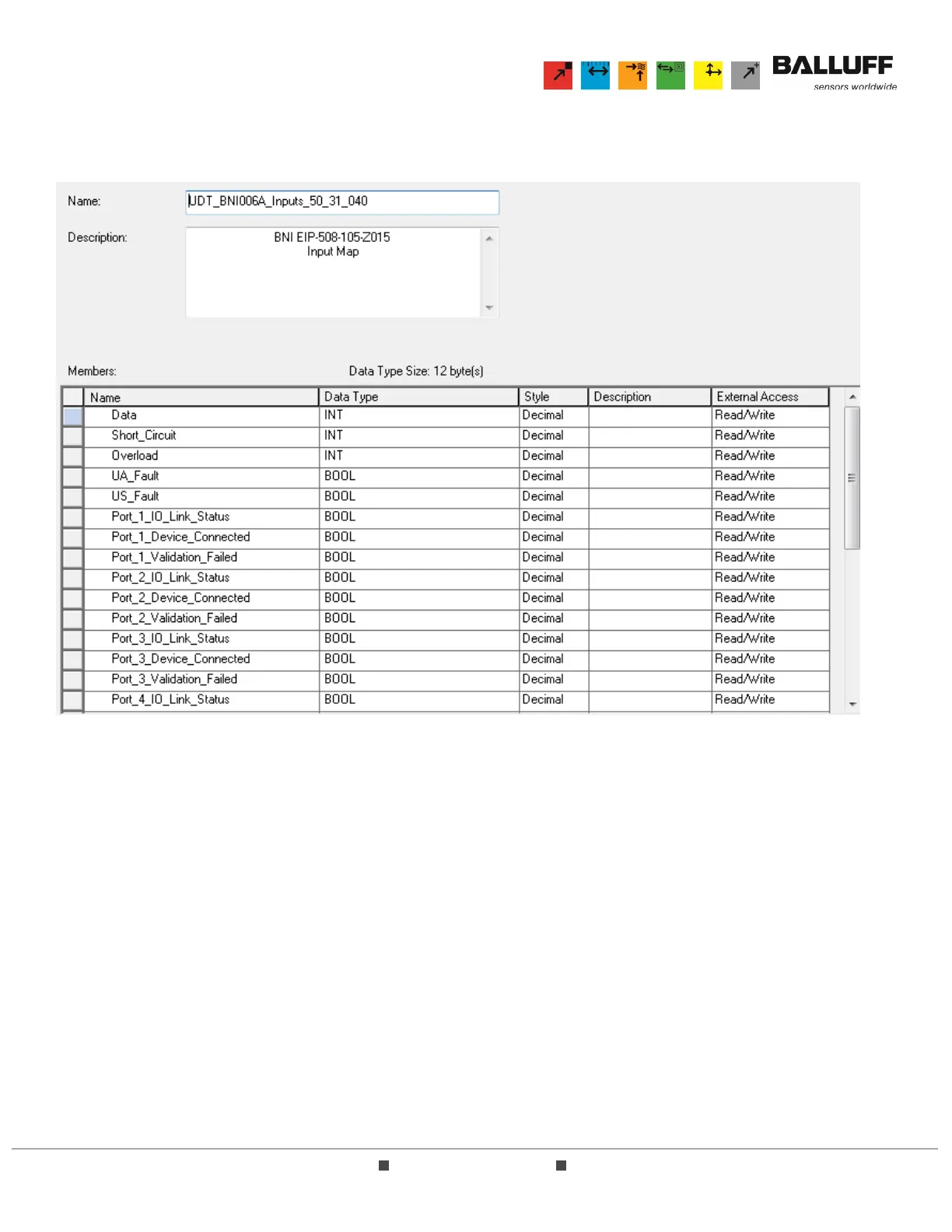
4.3 The Input UDT (UDT_BNI006A_Inputs_50_31_040) consists of all inputs associated with the BNI004A
block. A description of this UDT and its function is included here:
4.3.1 Data – this is a single 16-bit INT register that contains all discrete input data bits. If a port is
configured in IO-Link mode, the indicated result is 0.
4.3.2 Short_Circuit – this is a single 16-bit register that contains all discrete short circuit bits. These
bits indicate a short circuit between pins 1 and 3 on stated port.
4.3.3 Overload – this is a single 16-bit register that contains all discrete overload bits. These bits
indicate an overload has occurred on the indicated port and pin number. Note that these bits
will only function if the port is configured as an output.
4.3.4 UA_Fault – this Boolean value indicates whether auxiliary power is currently applied to the
BNI004A device’s output points. This bit is typically used to indicate an Emergency Stop has
occurred.
4.3.5 US_Fault – this Boolean value indicates whether sensor power is currently applied to the
BNI004A device.
4.3.6 Port_x_IO_Link_Status – (x = 1, 2, 3, or 4) this Boolean value indicates whether the indicated
Port (1-4) has been placed in IO-Link mode.
4.3.7 Port_x_Device_Connected – (x = 1, 2, 3, or 4) this Boolean value indicates whether the
indicated Port (1-4) has an operational IO-Link device connected to the port.
4.3.8 Port_x_Validation_Failed – (x = 1, 2, 3, or 4) this Boolean value indicates whether the indicated
Port (1-4) has passed the validation type as defined in the Configuration UDT (see Section 4.5).