(800) 543-8390 FAX (859) 727-8506 www.balluff.com
AOI_BNI006A_50_31_040 User Guide Page 17 of 26
5.0 Software Validation
5.1 If the preceding instructions (5.0 Instructions) have been successfully completed, the software module
will be integrated into the RSLogix5000 project and it will be ready to use. The user will be able to
verify proper operation of the AOI by monitoring the transition of a controller-scoped tag and its
corresponding real world device. This section describes a sampling technique that will verify the proper
operation of one input bit, one output bit, and a configuration parameter.
5.2 This example describes how to validate the transition of a controller-scoped input tag.
5.2.1 This example uses Port 6, Pin 4 (Input buffer byte 0, bit 6) although any input bit will suffice.
Note that all I/O points are freely configurable as either inputs or outputs and will respond to
logic accordingly. The key point of this example is to ensure that the AOI bit corresponding to
the selected input bit follows it. Place a device (discrete sensor or jumper wire) between pins 1
and 4 on Port 6 to cause this Input bit to transition to ON or “high”. This bit can be viewed in the
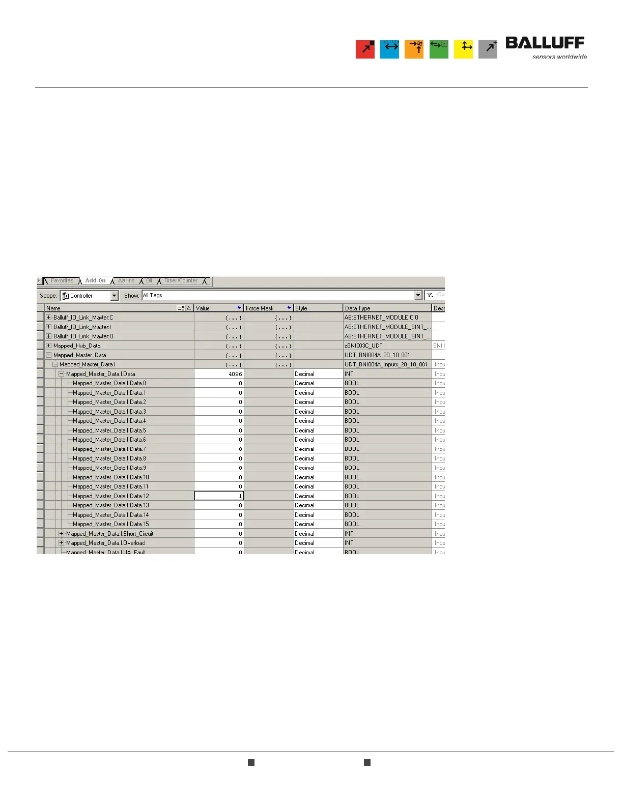
Controller scope tags as shown below:
Note that when the AOI module was used in the logic, the parameter Mapped_BNI_EIP_502_Data was
assigned to a tag named “Mapped_Master_Data”.
5.2.2 While this bit (Mapped_Master_Data.I.Data.12) is ON or “high”, the corresponding LED on the
I/O block should be lit. If this is not the case, please refer to Section 7.0 Troubleshooting.