(800) 543-8390 FAX (859) 727-8506 www.balluff.com
AOI_BNI006A_50_31_040 User Guide Page 18 of 26
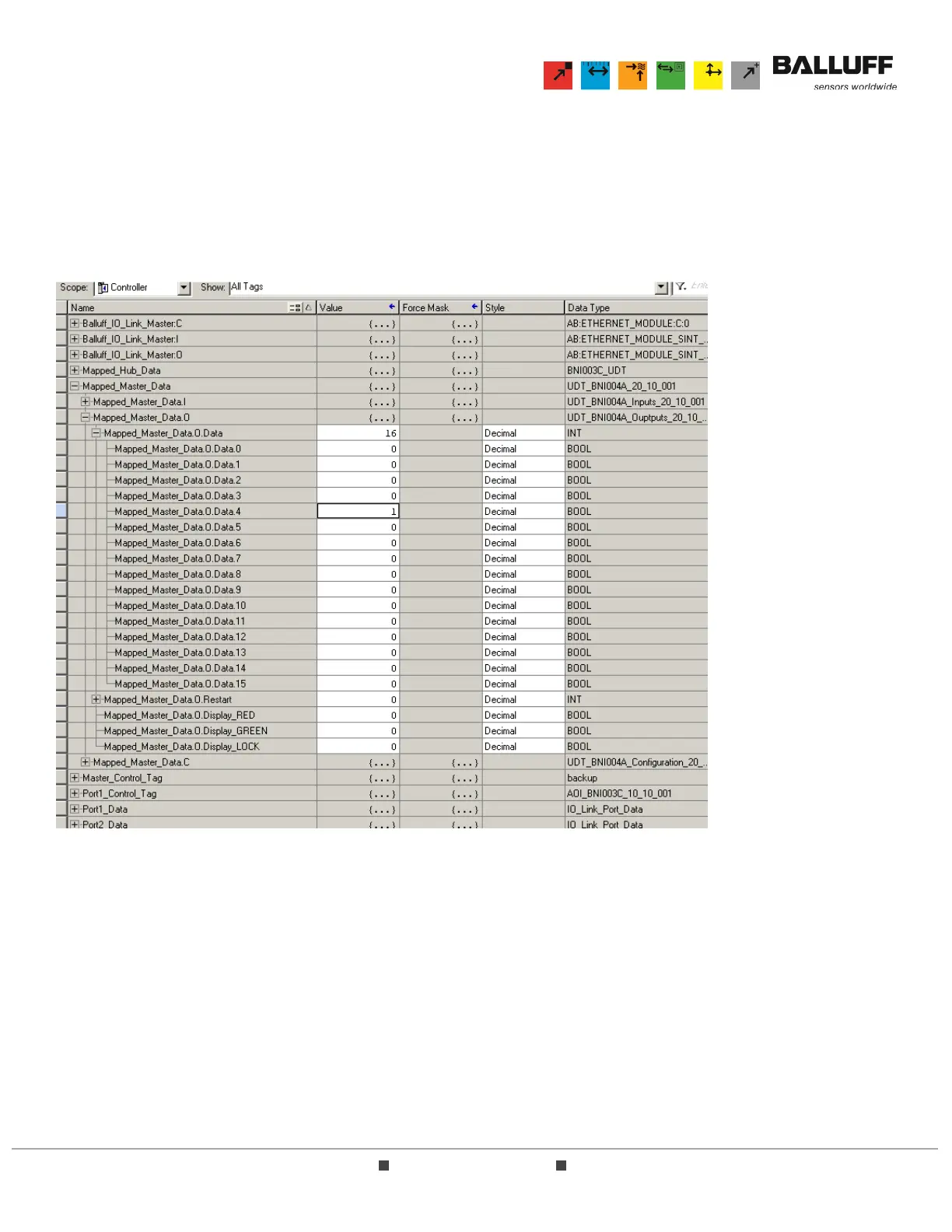
5.3 This example describes how to validate the transition of a controller-scoped output tag.
5.3.1 This example uses Port 4, Pin 4 (Input buffer byte 0, bit 4) although any output bit will suffice.
Note that all I/O points are freely configurable as either inputs or outputs and will respond to
logic accordingly. The key point of this example is to ensure that the AOI bit corresponding
follows the selected output bit. Place a device (pilot light, voltage meter or other discrete output
device) between pins 1 and 4 on Port 4, then transition the output bit to ON or “high”. This bit
can be viewed in the Controller scope tags as shown below:
Note that when the AOI module was used in the logic, the parameter Mapped_BNI_EIP_502_Data was
assigned to a tag named “Mapped_Master_Data”.
5.3.2 While this bit is ON or “high”, the discrete output device should transition to its ON state,
indicating that power is being passed to the device.
5.3.3 While this bit is ON or “high”, the corresponding LED on the I/O block should be lit. If this is not
the case, please refer to Section 7.0 Troubleshooting.
5.3.4 After confirming the operation of this output bit, return the bit to “low” or OFF to ensure that the
operation of logic is not affected.