Do you have a question about the Balluff BNI EIP-502-105-Z015 and is the answer not in the manual?
Describes the purpose of the BNI EIP module and its connection to EtherNet/IP.
Details the conventions used for enumerations, actions, syntax, and cross-references.
States the BNI EIP module is for connecting to an EtherNet/IP network.
Notes that installation and startup must be done by trained specialists.
Covers commissioning, inspection, authorized personnel, intended use, and malfunctions.
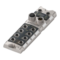
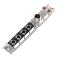
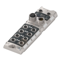
Provides an overview of the BNI EIP module with labeled ports and indicators.
Describes how the module is attached using M6 screws and isolation pad.
Details Power Supply, Grounding, Ethernet, I/O, and IO Link ports.
Lists housing material, enclosure rating, supply voltage, ports, dimensions, mounting, and weight.
Specifies operating temperature, storage temperature, EMC, and shock/vibration standards.
Details supply voltage, ripple, and input current at 24V.
Lists Ethernet IP port, cable types, data rate, max cable length, and flow control.
Explains the module status and port LEDs.
Describes datasizes for input, output, and config data for the Control System.
Maps configuration data string, showing module and IO Link port configurations.
Details the mapping of 200 bytes of input data for standard and IO Link ports.
Details the mapping of 134 bytes of output data for standard and IO Link ports.
Introduces the module's display and address settings.
Shows default IP, Subnet mask, and Gateway address values.
Explains the display controls and visualization elements.
Explains symbols used in display flow-charts for functionality.
Illustrates the module startup sequence and displayed information.
Shows the main menu structure and navigation for IP Config and Module Information.
Details the IP setup modes (STATIC, DHCP, FACTORY) and navigation.
Explains IP, Subnet, and Gateway configuration steps and saving values.
Describes how to scroll through module information like product name and MacID.
Covers fast scrolling, leaving screens, configuration differences, ping display, and LED functions.
Introduces the internal webserver for information and configuration.
Details getting information and configuring connected IO Link devices.
Describes configuring the module, network parameters, and user-defined texts.
Lists the components included with the BNI EIP module.
Explains the structure of the product order code.
Provides product ordering code and corresponding order code.
| Product Name | BNI EIP-502-105-Z015 |
|---|---|
| Category | Control Unit |
| Communication Protocol | EtherNet/IP |
| Operating Voltage | 24 VDC |
| Operating Voltage UB min. | 18 VDC |
| Operating Voltage UB max. | 30 VDC |
| Input Voltage | 24 VDC |
| Number of Inputs | 16 |
| Number of Outputs | 0 |
| Number of Channels | 16 |
| Protection Class | III |
| Protection Type per EN 60529 | IP67 |
| Width | 30 mm |
| Connection Type | M12 |
| Storage Temperature | -25...70 °C |