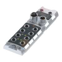
There are 200 bytes of Input data. Have a look at the tables below to see the mapping of the
process data inputs.
Process data inputs on standard Inputs
Process data inputs on IO Link Port 1
Process data inputs on IO Link Port 2
Process data inputs on IO Link Port 3
Process data inputs on IO Link Port 4
Input data
I04
Input on port 0 pin 4
If a port is configured as an IO
Link port, result is 0.
Short circuit status
Short circuit between Pin 1 and 3
on stated port
Overload status
O04
Overload on port 0 pin 4
Only if port is configured as output
Power status
PS: Sensor power
PA: actor power
IO Link Port 1 Input data
IO-Link status
IOL: Port in IO Link Mode
DC: Device connected
0: reserved
IO-Link Error
VF: Validation failed
0: reserved
The data of the other IO Link ports has the same structure and follows here

 Loading...