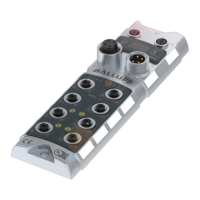
Balluff Network Interface EtherNet/IP™, BNI EIP-502-105-Z015
www.balluff.com
3.2. Mechanical
connection
The module is attached using 2 M6 screws and 2 washers.
Isolation pad as accessory available
3.3. Electrical
connection
IN
7/8”, male
OUT
7/8” female
Module / sensor power supply
GND Module / sensor power supply
GND actuator power supply
Note
Provide sensor/bus power and actuator power from separate power sources if
possible.
Total current <9A. The total current of all modules may not exceed 9A even
when daisy chaining the actuator supply.
Note!
The FE connection from the housing to the machine must be low-impedance
and kept as short as possible.

 Loading...