Balluff Network Interface EtherNet/IP™, BNI EIP-502-105-Z015
www.balluff.com
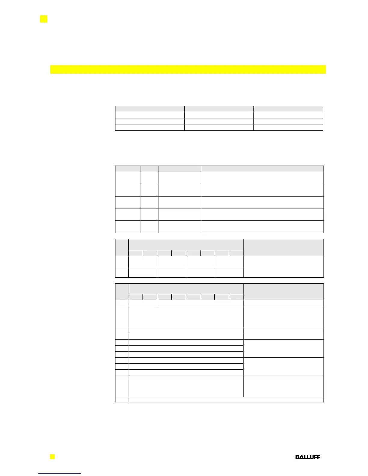
Please enter the following values to your Control System. They describe the datasizes for
input, output and config data.
In the following tables you can see the mapping of the configuration data string. The default
values which are stated below describe a configuration with IO Link function on Pin 4 and
standard input function (normally open) on Pin 2 of each IO Link port. The other Ports does
not get configured by config data string, the function of standard I/O ports is set by process
data (see 6.1 - Process Data Inputs)
General configuration for the whole module
(see 0 - Module Configuration)
Configuration for the IO-Link Port 1
(see 0 - IO Link Port Configuration)
Configuration for the IO-Link Port 2
(see 0 - IO Link Port Configuration)
Configuration for the IO-Link Port 3
(see 0 - IO Link Port Configuration)
Configuration for the IO-Link Port 4
(see 0 - IO Link Port Configuration)
Port function
0x00: Standard I/O
0x01: IO-Link
IO Link Port
Configuration
(optional)
Validation type
0 no validation
1 compatible (VID + DID)
2 identical (VID + DID + SerNum)
Parameter server
0x8X Enable
0xX1 Upload enable
0xX2 Download enable
The data of the other IO Link ports has the same structure and follows here

 Loading...


