(800) 543-8390 FAX (859) 727-8506 www.balluff.com
AOI_BNI006A_50_31_040 User Guide Page 23 of 26
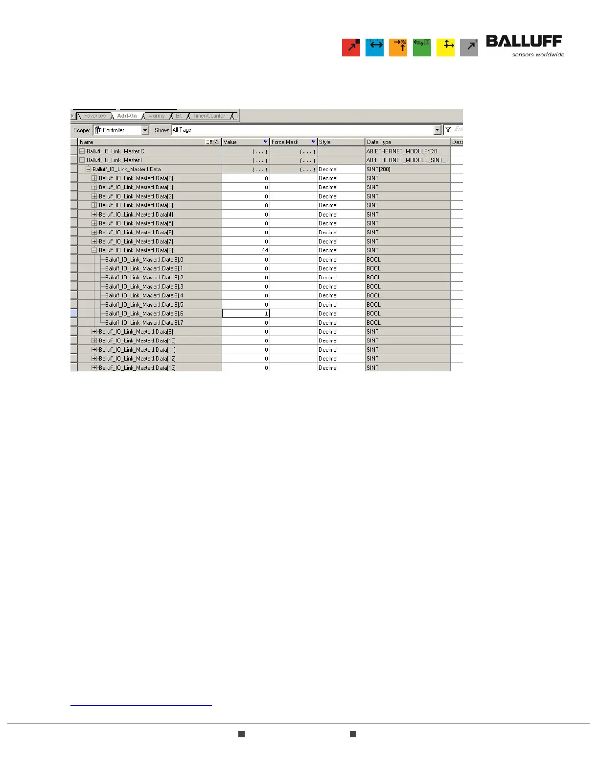
6.2.2 To confirm the raw data for this same input bit, you must observe the Input buffer of the IO-Link
master. Since this BNI0039 hub is connected to Port 1 of the master, the subject bit should be
byte 8, bit 6 as shown here:
Note that byte 8 corresponds only to Port 1 on the BNI004A master. This input bit will be indicated in
byte 56 (Port 2), byte 104 (Port 3), or byte 152 (Port 4).
6.3 If all system components are consistent with those described in Section 6.1 above and the raw data is
being received properly in RSLogix5000 but the user does not view AOI data as described in Section
5.1 above, additional steps can be taken to verify the proper operation of both the software
configuration and the hardware system and components.
6.3.1 To validate the software configuration:
6.3.1.1 Ensure that the Balluff hardware is communicating properly with the Logix processor. A
communication error is easily identified when RSLogix5000 is online with the processor
as the network hardware will be identified with a yellow warning triangle when the
communication fails.
6.3.1.2 Start a new RSLogix5000 project using only the Balluff hardware and AOI module. This
should eliminate any potential software conflicts.
6.3.2 To validate the hardware system and components:
6.3.2.1 Remove all other hardware nodes from the Ethernet network so that only the Balluff
module and the Logix processor are connected.
6.3.2.2 Verify that any switches used in the network layout are operating properly and have solid
connections.
6.3.2.3 Identify and remove any potential sources of electrical noise or interference that might
impede network communication.
6.4 If the system still does not respond properly, please contact the Balluff Technical Support Group at
technicalsupport@balluff.com.