WWW.BALLUFF.COM • 1-800-543-8390
5
™
BTL5-A/C/E/G__-M____-B/Z-S32/KA__
Micropulse Linear Position Transducer
Analog Output-Rod Style
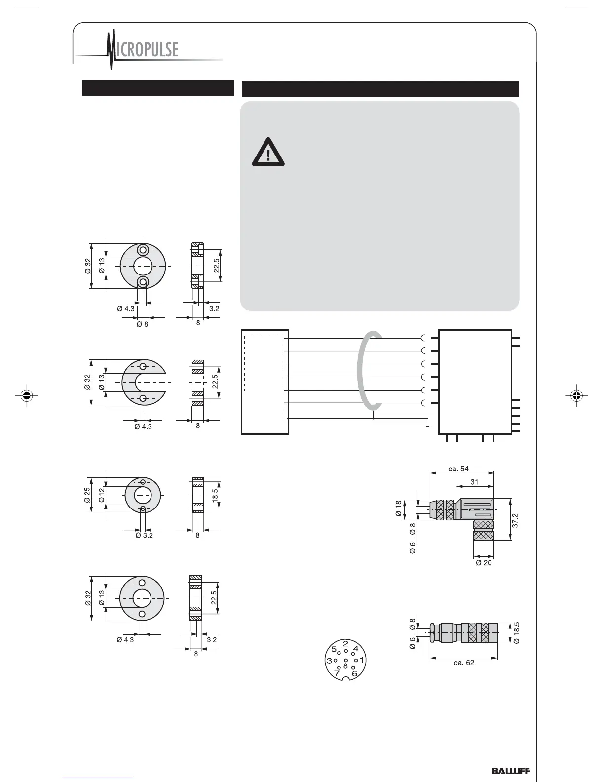
3 Installation (cont.)
3.3 Magnets, Installation
A magnet is required for each
transducer. This must be ordered
separately. Fig. 3-4.
For mounting the magnet we
recommend to use non-magnetizable
material. Fig. 3-1.
Fig. 3-4: Magnet (optional)
BTL-P-1013-4R
BTL-P-1013-4S
BTL-P-1012-4R
Fig 3-5: Spacer
System and control cabinet
must be at the
same ground
potential.
To ensure the
electromagnetic compatibility
(EMC) which Balluff warrants
with the CE Mark, the following
instructions must be strictly
followed.
BTL transducer and the control
must be connected using
shielded cable.
Shielding: Copper filament
braided, 80% coverage.
The shield must be tied to the
connector housing in the BKS
connector (Fig. 4-3); see instructions
accompanying the connector.
In the cable version the cable shield
is connected to the housing in the
PG fitting.
The cable shield must be grounded on
the control side, i.e., connected to the
protection ground.
Pin assignments can be found in
Table 4-1. Connections on the
controller side may vary according to
the controller and configuration
used.
4 Wiring
YE
GY
PK
GN
BU
BN
Controller with
analog input
BTL5-A11-
...KA_ _
not used
0 V
10...0 V
0...10 V
GND
+24 V
Fig. 4-1: BTL5-A11...KA_ _ with controller, wiring example
When routing the cable between
the transducer, controller and
power supply, avoid proximity to
high voltage lines to prevent noise
coupling. Especially critical is
inductive noise caused by AC
harmonics (e.g. from phase-
control devices), against which
the cable shield provides only
limited protection.
Cable length max. 20 m; Ø 6 to
8 mm. Longer lengths may be
used if construction, shielding and
routing are such that external
noise fields will have no effect on
signal integrity.
BKS connector, view
towards solder side of
female BKS-S 32M-00
or BKS-S 33M-00
Fig. 4-2: Pin assignments BKS,
connector type BTL
straight BKS-S 32M-00
right-angle BKS-S 33M-00
Fig. 4-3: Connector (optional)
Cable entry (PG 9 fitting)
Note the following when making electrical connections:
Z_Analog_122003.pmd 12/11/2003, 3:47 PM5

 Loading...