WWW.BALLUFF.COM • 1-800-543-8390
3
™
BTL5-A/C/E/G__-M____-B/Z-S32/KA__
Micropulse Linear Position Transducer
Analog Output-Rod Style
2 Function and Characteristics
The magnet defines the measured
position on the waveguide. An
internally generated INIT pulse
interacts with the magnetic field of
the mag-net to generate a
magnetostrictive torsional wave in
the waveguide which propagates at
ultrasonic speed.
The torsional wave arriving at the
end of the waveguide is absorbed
in the damping zone. The wave
arriving at the beginning of the
waveguide creates an electrical
signal in the coil surrounding the
waveguide. The propagation time of
the wave is used to derive the
position. Depending on the version
the corresponding value is output
as a voltage or a current either with
rising or falling characteristic. This
process takes place with measur-
ing high precision and repeatability
within the stroke range defined as
nominal stroke length.
At the rod end is a damping zone,
within which no reliable signal is
available, but which may be
entered by the magnet.
The electrical connection between
the transducer, the processor/
controller and the power supply is
via a cable,
3 Installation
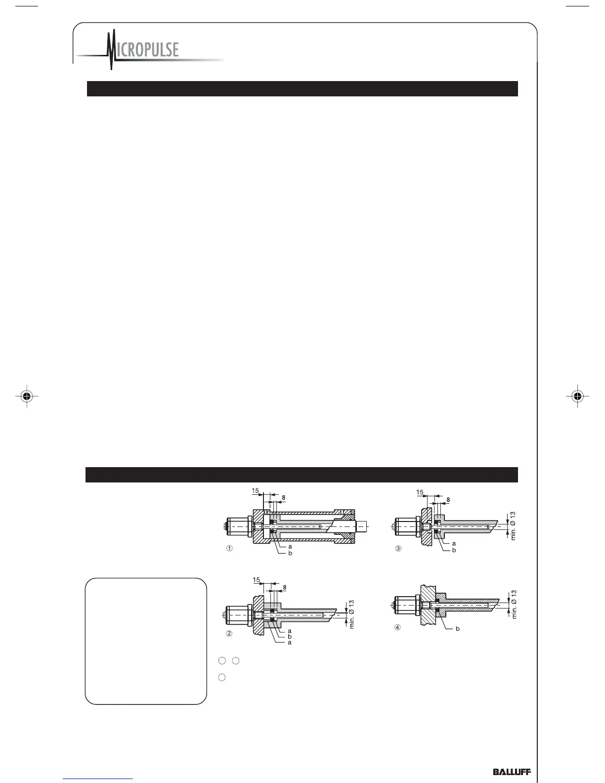
3.1 Mounting
When possible, use non-
magnetizable material for
attaching the transducer and
magnet ring. Fig. 3-1.
When attaching the
transducer to
magnetizable materials,
appropriate measures
must be taken to protect
against magnetic
disturbances (Fig. 3-1).
Note the recommended
distance of the trans-
ducer and cylinder from
strong, external magnetic
fields.
for magnetizable materials
for non-magnetizable materials
a = Spacer made of non-magnetizable
materials
b = Magnet
Fig. 3-1: Mounting
which depending on the version
is either fixed or connected
using a female connector.
Dimensions for installing the
Micropulse transducer:
Fig. 3-2
Dimensions for installing the
magnet: Fig. 3-4
2.3 Available stroke lengths
and magnets
To provide for optimum fit in
any application, a wide range of
standard stroke lengths and
magnets in various form factors
are available. Magnets must
therefore be ordered separately.
See inside front cover for
available stroke lengths.
2.1 Characteristics
Micropulse transducers
feature:
- Very high resolution,
repeatability and linearity
– Immunity to shock,
vibration, contamination
and electrical noise
– An absolute output signal
– Automatic signal
regulation
– 100 % adjusting range
- Removable calibration
device
– 2 kHz update rate
– Error information via output
signal
– Pressure rated to 600 bar
– IP 67 per IEC 60529
2.2 Function
The transducer contains a
tubular waveguide enclosed by
an outer stainless steel rod. A
magnet attached to the
moving member of the
machine or to the cylinder
piston is moved over the rod
and its position constantly
updated.
4
1
3
-
Z_Analog_122003.pmd 12/11/2003, 3:47 PM3

 Loading...