Bandit
87
Copyright 4/21
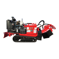
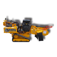
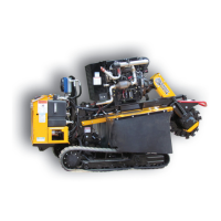
MODELS 2550/2550T
2550 - MANUAL / SWING OUT CONTROLS
Make sure to order components according to tting type, ttings may vary on all components.NOTICE
Hydraulic components, ttings, hoses will vary depending on optional equipment.
Order by physical description.
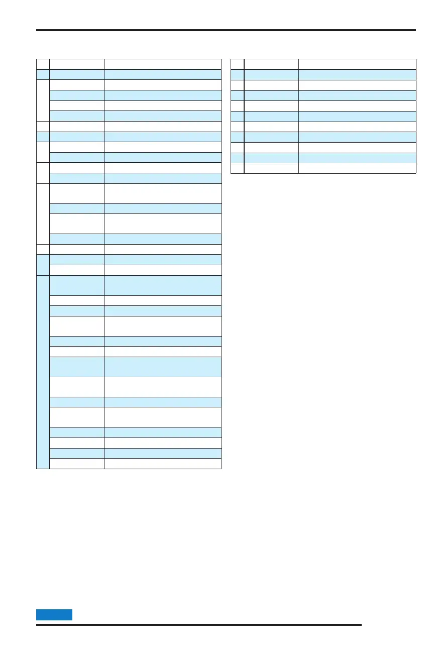
# Part Number Description
1 See pp 78-79 Hydraulic Tank
2
900-3951-31 In Tank Filter (Start 11/12)
900-3951-32 Filter Element Only (Start 11/12)
900-3938-23 In Tank Filter (Pre 11/12)
900-3938-96 Filter Element Only (Pre 11/12)
3 900-3944-78 Tank Strainer
4 900-3943-65 1/4” Ball Valve
5
900-3982-94 Cutter Wheel Pump (Start 1/17)
900-3955-97 Cutter Wheel Pump (Pre 1/17)
6
900-3955-82 High Pressure Filter
900-3944-57 Filter Element Only
7
900-3959-06
Cutter Wheel Motor
(Start 4/14)
900-3951-17 Cutter Wheel Motor (Pre 4/14)
900-3955-99
Cutter Wheel Motor Manifold
Relief
900-3956-04 Relief Only
8 See Check Sheet Auxiliary Pump
9
900-3969-57 5 Function Valve Bank
900-3969-56 4 Function Valve Bank
10
900-3982-15
Divider/Brake Manifold
Assembly
900-3928-25 Brake Hand Pump (HP1)
900-3945-71 Brake Release Needle (NV1)
900-3945-72
Drive/Swing Speed Control
Needle (NV2)
900-3945-73 Brake Release Check (CV1)
900-3945-74 Brake Release Shuttle (LS1)
900-3957-19
Dual Pressure Override Check
(DC1-DC3)
900-3929-09
Drive/Swing Counter Balance
(CBV1, CBV2)
900-3945-79 Flow Divider (FD1)
900-3956-99
.030” Brake Release Orice
(ORF2)
900-3957-20 Swing Shuttle (LS2)
900-3957-21 Swing Pilot Valve (PD1, PD2)
900-3957-22 Swing Flow Control (FR1)
900-3957-23 Swing Tank Check (CV2)
# Part Number Description
11 900-3952-11 Oil Cooler
12 900-3947-20 Braking Motor
13 900-3947-21 Non-Braking Motor
14 900-3937-68 Steering Cylinder
15 900-3940-29 Cutter Wheel Lift Cylinder
16 900-3935-35 Dump Valve Block
17 900-3965-87 Dual Cross Over Relief
18 900-3958-80 Swing Cylinder
19 900-3002-51 Dual Counter Balance Valve
20 900-3946-87 Blade Cylinder
HYDRAULIC DIAGRAM