141/21
MODEL 75 OPERATION
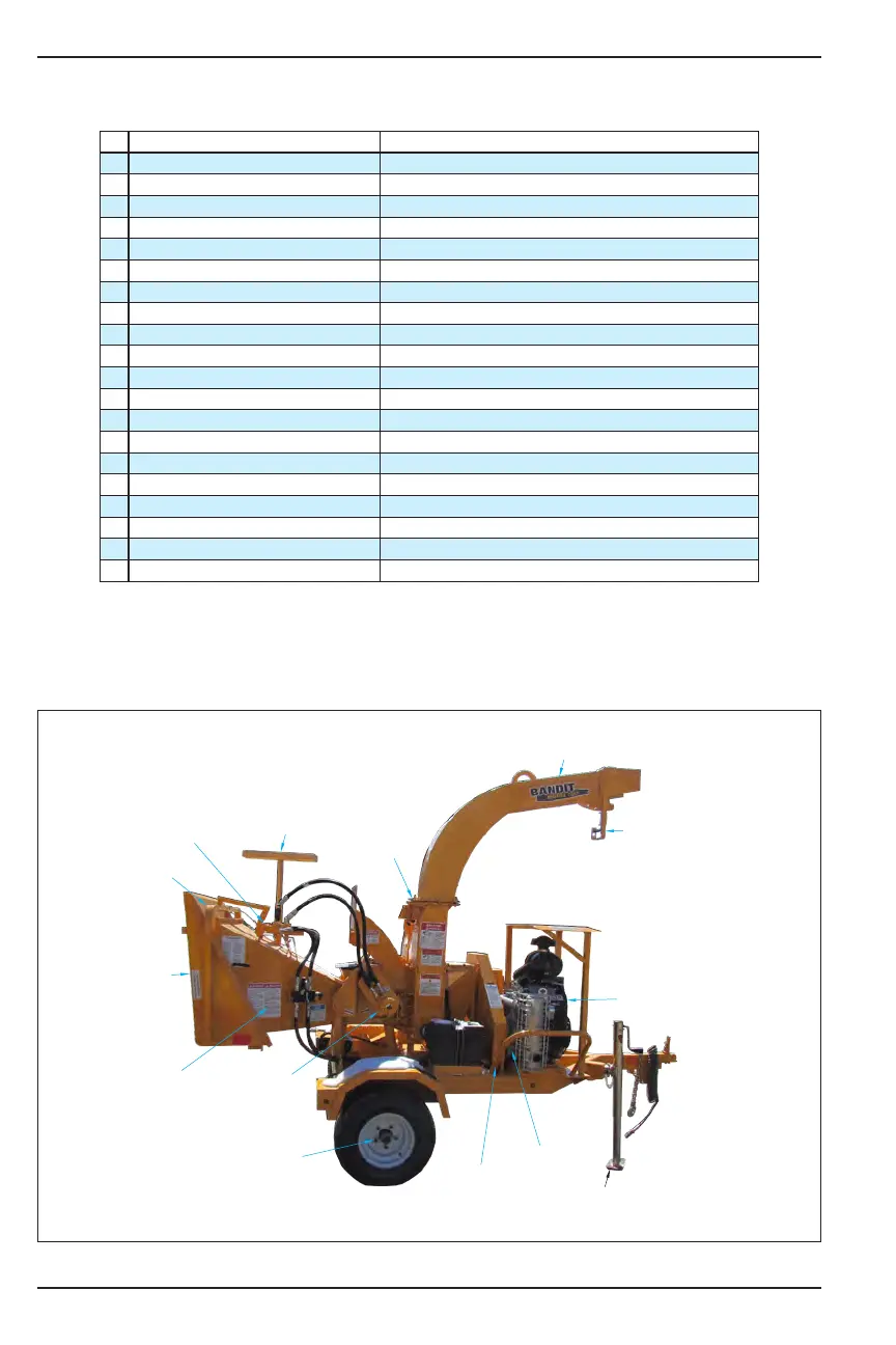
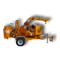
Basic Location of Controls and Components
CONTROLS
# Description Location
1
Foot Pad Jack Discharge end, on tongue
2
Clutch Handle (If equipped) Drive side, on engine
3
Chipper Belts / Pump Belts Drive side
4
Lug Nuts Drive side / Radiator side, on tires
5
Feedwheel Motor Coupler Drive side, on top and bottom yoke
6
Infeed Hopper Infeed hopper end
7
Folding Infeed Tray Infeed hopper end
8
Feedwheel Control Bar Infeed hopper end, around infeed hopper
9
Hydraulic Control Valves Infeed hopper end, on top of the infeed hopper
10
Wooden Push Paddle Radiator side, on the infeed hopper
11
Swivel Discharge Drive side
12
Discharge Chute Discharge end
13
Discharge Flipper Adjuster Discharge end, towards the end of the discharge
14
Autofeed Controls On engine
15
Engine Controls, Adjusters On engine
16
Electric Engine Throttle Adjuster On engine
17
“Bandit” Lever Throttle Adjuster On engine
18
Optional Feedwheel Trap Door Below optional bottom feedwheel (not shown)
19
Adjustable Height Discharge Drive side, on discharge (not shown)
20
Knives & Hardware On disc (not shown)
1
13
12
10
9
8
7
5
6
4
3
2
11
14,15,16,17