12 P/N 43298 rev. E
Banner Engineering Corp. •Minneapolis,MNU.S.A.
www.bannerengineering.com•Tel:763.544.3164
MINI-ARRAY
®
InstructionManual
Status Indicators
(See Section 6.2 for
more information)
The following status LEDs are located on the front panel:
OUTPUT1(red)(nameandfunctionvarydependingonmodel):Indicatesactiveoutput
ALARM(red):IndicatesthatOutput2or16isactive(dependingonmodel)
GATE(red):IndicatesvoltageisappliedtoGATEinput
ALIGN(green):Indicatessensoraligned(excessgain>1x)
Plus three diagnostic LEDs:
DIAG1(green):Indicatespowerisappliedtothemodule
DIAG2(red):Indicatesreceiverfailure
DIAG3(red):Indicatesemitterfailure
Sensor Scan Time
For all models:
55microsecondsperbeamplusprocessingtime.
Theprocessingtimeisdependentonthescananalysisandthenumberofactiveoutputs.
Thistimingassumesastraightscan,continuous,andTBBmode.
MAC-1, MACN-1 & MACP-1:1millisecondprocessingtime.
MACV-1 & MACI-1:
1.5millisecondsprocessingtime.
MAC16N-1 & MAC16P-1:2.3to7millisecondsprocessingtime.
Construction
Polycarbonate
Environmental Rating
NEMA1(IP20)
Operating Conditions
Temperature:
-20°to+70°C(-4°to+158°F)
Maximum Relative Humidity:95%(non-condensing)
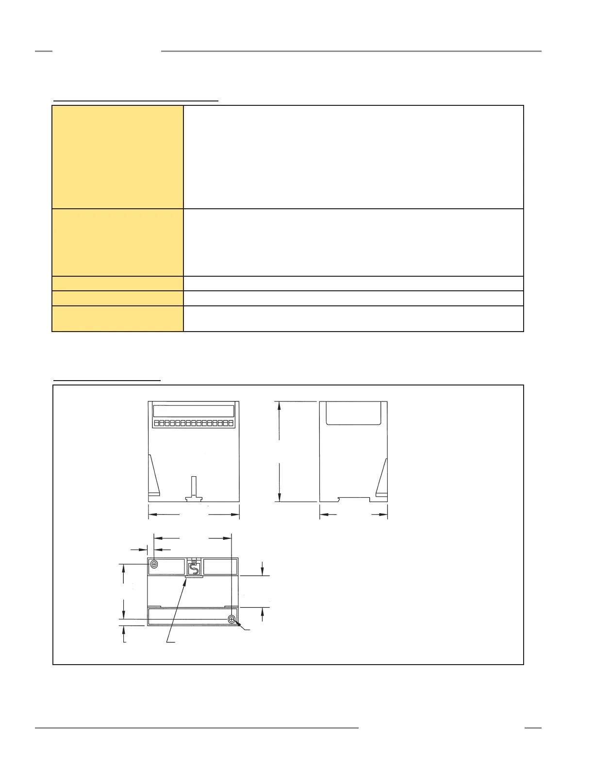
2.4 Controller Dimensions
Figure 2-2. Control module dimensions and mounting hole locations
75.0 mm
(2.95")
60.8 mm
(2.40")
7.1 mm
(0.28")
Din mounting tab
(supplied)
Slot for screws (2)
M3.5 x 0.6 mm (2)
35.0 mm
(1.38")
Din mounting slot
100.0 mm
3.94"
85.3 mm
3.36"
7.4 mm
(0.29")
110.0 mm
(4.33")
Combo Head (Phillips/Slotted Screws
M3.5 x 0.6 mm x 14 mm (2 ) (#6 x 0.5" equivalent) (supplied)
M3.5 Washers (2) (#6 equivalent) (supplied)
M3.5 mm x 0.6 mm Nuts (2) (#6 equivalent) (supplied)
Recommended torque is
16-20 in -lbs on mounting screws
Specifications
2.3 Controller Specifications (continued)