P/N 43298 rev. E 13
Banner Engineering Corp. •Minneapolis,MNU.S.A.
www.bannerengineering.com•Tel:763.544.3164
MINI-ARRAY
®
InstructionManual
Installation and Mechanical Alignment
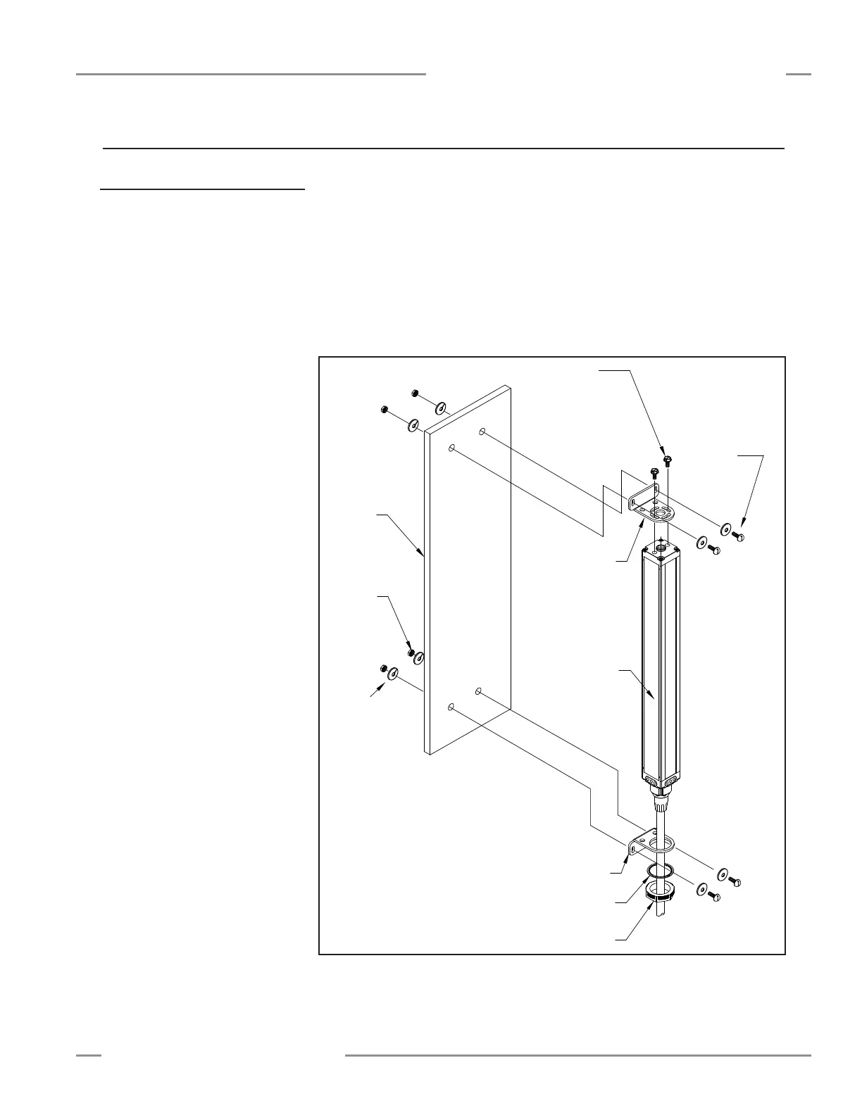
3.1 Emitter and Receiver Mounting
BannerMINI-ARRAYemittersandreceiversaresmall,lightweight,andeasytomount;themountingbrackets(supplied)allow±30
degreesrotation.
Fromacommonpointofreference,makemeasurementstopositiontheemitterandreceiverinthesameplanewiththeir
midpointsdirectlyoppositeeachother.MounttheemitterandreceiverbracketsusingtheM4x0.7x14mmboltsandassociated
mountinghardware(allsupplied).SeeFigure3-1.
Althoughtheinternalcircuitryoftheemitterandreceivercanwithstandheavyimpulseforces,vibrationisolatorscanbeused
insteadoftheM4boltstodampenimpulseforcesandpreventpossibledamagefromresonantvibrationoftheemitterorreceiver
assembly.TwodifferentAnti-VibrationMountingKitsareavailablefromBannerasaccessories.
Figure 3-1. MINI-ARRAY emitter and receiver mounting hardware
Emitter
or
Receiver
Mounting
Mounting
Bracket
Surface
M4
Nut (4)
Washer (2)
with Compression
Slotted Hex Head
M4 x 10 mm
Bracket
Mounting
Nut
Washer
M4 x 14 mm
Screw with Flat
Washer
Compression
Washer (4)
Torque to
12 in. lbs.
(1.3 N-m)
3. Installation and Mechanical Alignment
P/N48955consistsof4anti-vibration
mounts(M4x0.7x9.5mm)and8
M4Kepsnuts.Thesemountsaremade
fromBUNA-Nrubberandaremore
resistanttochemicalsandoils.
P/N12847consistsof4anti-vibration
mounts(M4x0.7x9.5mm)and8
M4Kepsnuts.Thesemountsaremade
fromnaturalrubber,whichareless
chemicallyresistantthanthe48955
mounts,buthaveagreatersheerforce
specathighertemperature.