36 P/N 43298 rev. E
Banner Engineering Corp. •Minneapolis,MNU.S.A.
www.bannerengineering.com•Tel:763.544.3164
MINI-ARRAY
®
InstructionManual
System Operation
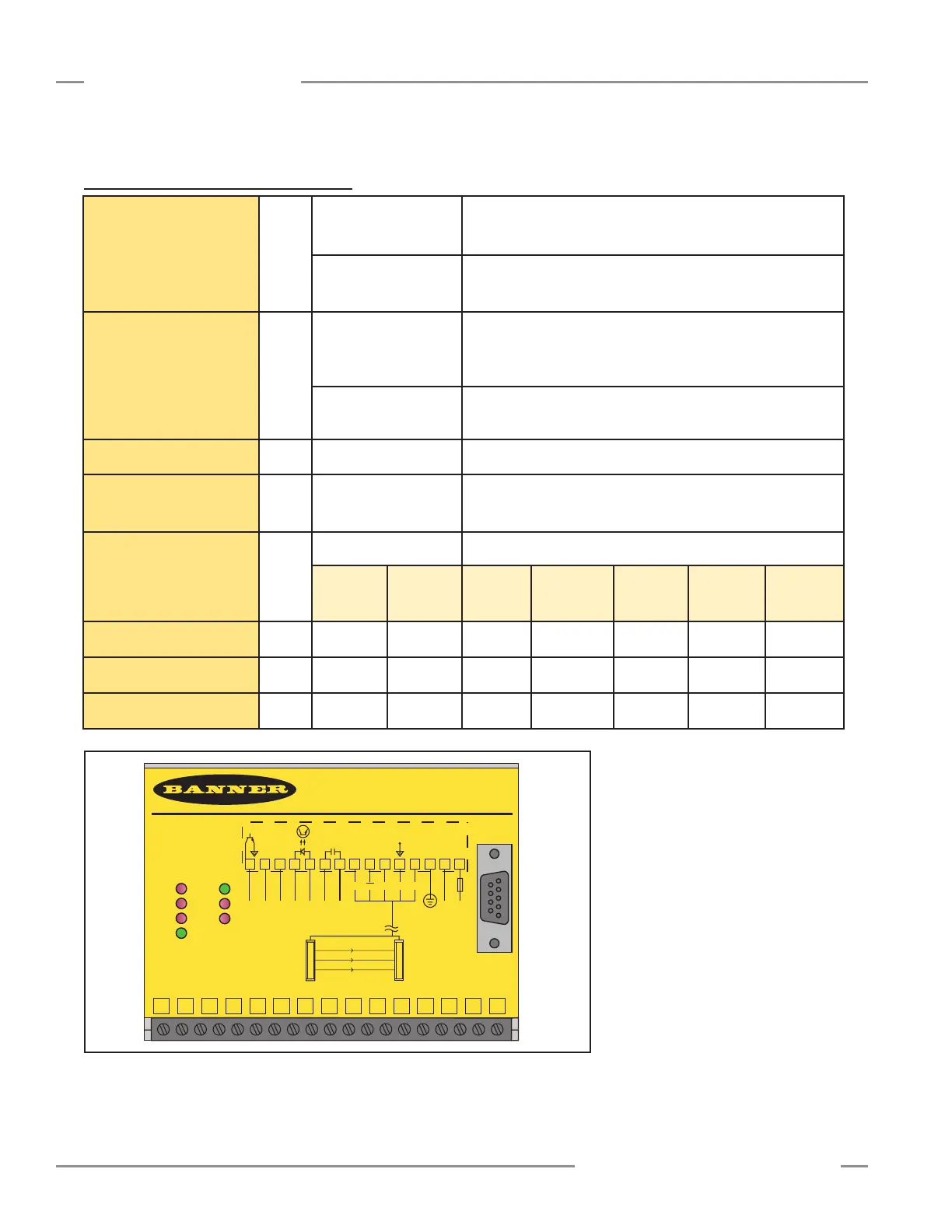
6.2 Controller Operating Status Indicators
MINI-ARRAY
CONTROLLER
2 - TX
3 - RX
5 - COM
RS-232
RS-232
MAC-1
OUT 1
ALARM
GATE
DIAG 1
DIAG 2
DIAG 3
ALIGN
POWER
15 14 13 12 11 10 9 8 7 6 5 4 3 2 1
15
30V
150mA
Max.
ALARM
500mA
Max
OUT 1
WH BK BU
5 Wires
BR- +
RS485
- +
10-30V DC
GATE
L2 L1
16-30V DC
1.2A Max.
14 13 12 11 10 9 8 7 6 5 4 3 2 1
T/R T/R DRN COM +12V F1
EMTR RCVR
Figure 6-2. Controller front panel
Output 1
(labeledOUT1,Vout,
Iout,OUTorOUT1
dependingonmodel)
Red
Models MAC-1,
MACP-1, MACN-1,
MACV-1, MACI-1:
displaysthestatusofOutput#1
Models MAC16N-1
MAC16P-1:
displaysthestatusthatatleastoneoutputisactive
Alarm
Red
Models MAC-1,
MACP-1, MACN-1,
MACV-1, MACI-1:
displaysthestatusofOutput#2.Output#2maybeassigned
toanAnalysisModeormaybeusedasasystemdiagnostics
Alarm,orasaTriggeralarmforgatinganotherMINI-ARRAY
System
Models MAC16N-1
MAC16P-1:
displaysthestatusofOutput#16
Gate
Red
All Models
displaysthestatusoftheGateinput
Align
Green
All Models
indicatespropersensoralignmentandaclearlightscreen.This
indicatorisONwhenthegreenorgreenandyellowLEDsofthe
receiverareON
Diag 1,2,3
All Models
usedincombinationtoindicatesystemstatusasshownbelow:
Normal
Condition
Receiver
Error
Emitter
Error
Emitter/
Receiver
Mismatch
Controller
Error
EEPROM
Error
ROM/RAM
Error
Diag 1
Green ON ON ON ON OFF OFF OFF
Diag 2
Red OFF ON OFF ON ON OFF ON
Diag 3
Red OFF OFF ON ON OFF ON ON