16 P/N 43298 rev. E
Banner Engineering Corp. •Minneapolis,MNU.S.A.
www.bannerengineering.com•Tel:763.544.3164
MINI-ARRAY
®
InstructionManual
Installation and Mechanical Alignment
1
+
–
+
–
10-30V dc
Gate
16-30V dc
1.2 A Max.
234
5
678
9
10131415
F1
BROWN
BLUE
DRAIN (BARE)
BLACK
WHITE
EMITTER and
RECEIVER CABLES
V- V+
RS485
Out 1
30V
150 mA
Max.
30V
150 mA
Max.
ALARM
Power
12 11
Com
1
+
–
10-30V dc
Gate
16-30V dc
1.2 A Max.
234
5678
9
10131415
F1
BROWN
BLUE
DRAIN (BARE)
BLACK
WHITE
EMITTER and
RECEIVER CABLES
V- V+
30V
150 mA
Max.
ALARM
0-10V
10 mA
V out 2
Power
12 11
Com Com
0-10V
10 mA
Max.
V out 1
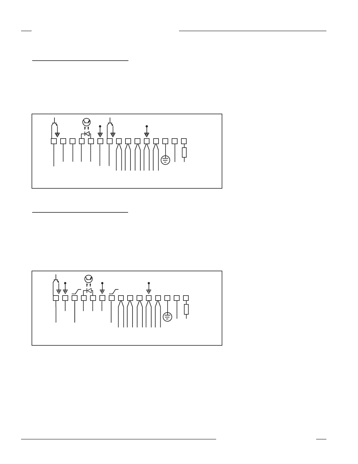
Figure 3-7. Model MACN-1 hookup
Figure 3-8. Model MACV-1 hookup
3.4.3 Model MACN-1 Controller Hookup
Output 1:Controllerterminal#9(OUT1)isanopen-collectorNPNtransistorswitch
ratedat30Vdcmax.,150mAmax.Itisprotectedagainstoverloadandshortcircuits.
Alarm:Controllerterminal#15(ALARM)isanopen-collectorNPNtransistorswitch
ratedat30Vdcmax.,150mAmax.Itisprotectedagainstoverloadandshortcircuits.
Bothoutputsarecurrentsinking.
3.4.4 Model MACV-1 Controller Hookup
Voltage outputs 1 and 2:Controllerterminals#9(Vout1)and#13(Vout2)are
analogvoltageoutputs.TheloadforanalogvoltageOutput#1shouldbetiedacross
terminals#9and#10.TheloadforanalogvoltageOutput#2shouldbetiedacross
terminals13and14.Bothswitchesareratedat10Vdcmax.,10mAmax.Both
outputsarevoltagesourcing.
Alarm:Controllerterminal#15(ALARM)isanopen-collectorNPNtransistorratedat
30Vdcmax.,150mAmax.,currentsinking.