July 17, 2023
Asset Monitoring Gateway With SNAP ID Instruction Manual
5
Chapter Contents
Wiring the AMG ................................................................................................................................................................................................... 5
AMG HMI Home Screen...................................................................................................................................................................................... 5
Commission and Assign Connected Sensors or Converters .............................................................................................................................. 6
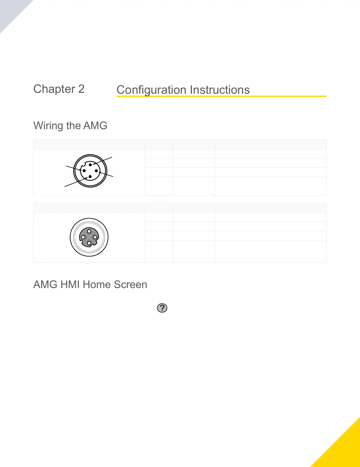
Wiring the AMG
4-pin M12 A-Code Male Pin Wire Color Description
1 Brown (bn) 10 to 30 V DC
2 White (wh) RS-485 + Serial
3 Blue (bu) Ground
4 Black (bk) RS-485 - Serial
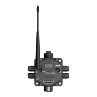
4-pin M12 D-Code Ethernet Female Pin Wire Color Description
1 white/orange Tx +
2 white/blue Rx +
3 orange Tx -
4 blue Rx -
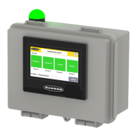
AMG HMI Home Screen
Customizethegatewayname,locatedonthetoptitlebar,bytappingEnter titleandtypinginacustomname.
For help information, click the help-information icon ( )inthetoprightcornerofthescreen.Touchtheglobeicontodis
play a QR code that takes you to the product information from Banner Engineering.
Thefourstatusiconsrepresentgroupsofsensingassets(upto20devices).Eachicon'scolorindicateswarnings,alarms,or
connectionstatuswithinthatgroup.Groupiconsarenameablefromwithinthegroupiconwindow.Selectanicontoviewthe
asset’sstatusoradditionalsensordata.
Configuration Instructions
© Banner Engineering Corp.