Manual 2100-746
Page 34 of 55
Test Mode
Two test modes are available on this controller, System
Test and Manual Test.
System Test
In System Test, all functionality configured for each
unit can be activated for 300 seconds beginning with
the lead unit. Each stage is advanced by a user-
activated button on the System Test screen. Stages
available include Blower, Cooling Stages 1 & 2, Electric
Heat Stages 1 & 2, Dehumidification, Humidification
and Heat Pump Stages 1 & 2. Stages available during
test will be dependent upon equipment configuration
and will only include the stages that are configured.
The user advances the unit via a user-activated button
on the System Test screen. The user can also increase
the time duration of any stage to 1200 seconds via a
button on the System Test screen. The user can also
terminate the test via a button on the System Test
screen at any time; if this is the case, all outputs will
be de-energized and the controller will return to the
Home screen and normal operation will resume.
During the System Test, the terminals designated
in the sequences in this document will become
active independent of space temperature or humidity
considerations while the System Test is active. Once
the timer expires for a stage in the System test, the
next stage will begin unless the duration has been
increased to 1200 seconds via the “Hold” button;
if this is the case. all outputs will be de-energized
and the controller will return to the Home screen and
normal operation will resume.
System Test will always start with unit 1 and priority to
stages will be as listed below:
1. Blower
2. Cooling Stage 1
3. Cooling Stage 2
4. Heat Pump Stage 1
5. Heat Pump Stage 2
6. Electric Heat Stage 1
7. Electric Heat Stage 2
8. Dehumidification
9. Humidification
Manual Test
In Manual Test, the user will be provided buttons on
the Manual Test screen corresponding to all outputs
designated to a configured unit and each configured
unit will have a tab assigned. As the output button is
activated, the corresponding terminal will be energized
for 500 seconds. Terminals include W1, W2, Y1, Y2,
O/B, A, D, H, Aux Out and G.
Network/Remote Connectivity
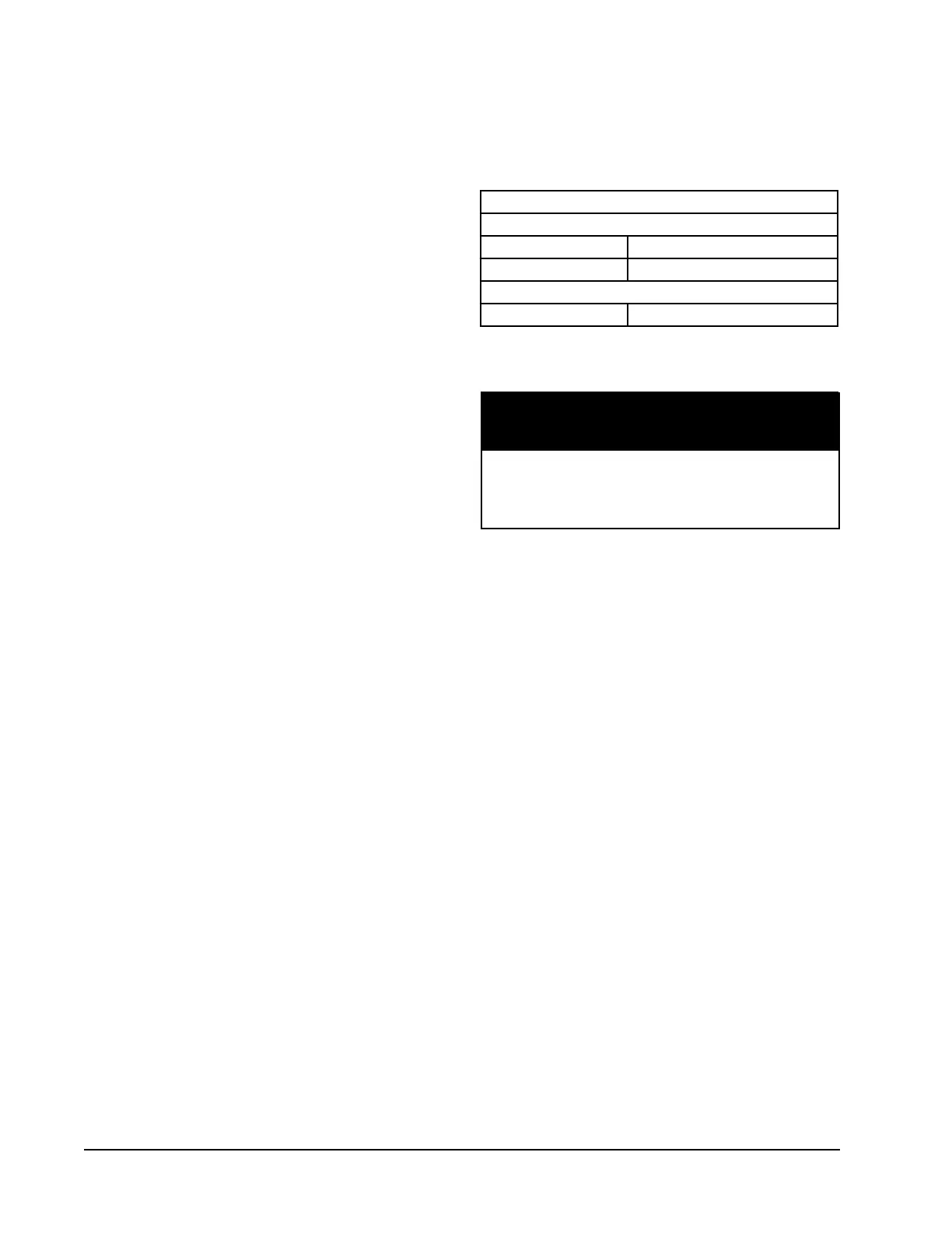
See Table 5 for the default network settings.
TABLE 5
Default Network Settings
Default Network Settings
IPv4
IP 192.168.1.67
Subnet 255.255.255.0
IPv6
IP 2001.00DB:AAAA:2222::14
Remote Connectivity
When connecting this product from a remote
location, ensure that the network connection
is secure and reliable.
IMPORTANT
The MC5000 series controllers have remote
connectivity available utilizing an Ethernet connection
located on the back of the touch screen display (see
Figure 17). Network configuration can be done from
the touch screen display or via the webpages and can
be configured for use on IPV4 and IPV6 networks.
Modbus TCIP and built-in webpages allow for easy
access to unit and controller information as well
as configuration settings. Updating the firmware is
available via the webpages.
Setup
Touch Screen Display IP Configuration
From the home screen, press the Setup menu button
(see Figure 18). In the Setup menu, press the IP
Configuration tab to navigate to the IP Configuration
page. On this page, the DHCP (enable/disable)
should be configured first. If DHCP is disabled,
the IPv4 address, IPv4 Subnet mask, IPv4 Default
gateway, IPv4 Primary DNS and IPv4 Secondary DNS
can be set by touching the dialog box and entering
information on the popup keypad. To configure the
IPv6 settings, the IPv6 tab on the right side of the
screen will need to be pressed to navigate to the IPv6
settings. Once settings are configured, the Apply
Settings tab must be pressed prior to navigating from
screen for the settings to be saved and applied. Once
settings are saved, the Return tab can be used to
return to the Setup menu.