Manual 2100-705B
Page 43 of 43
Remote Indoor Temperature/Humidity
Sensor Orientation
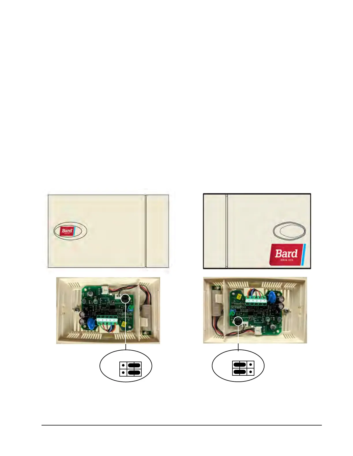
Current versions of the remote indoor temperature/
humidity sensor need to be installed with the shielded
cable wires entering the bottom of the back of the
sensor to connect to the sensor terminals (see Figure
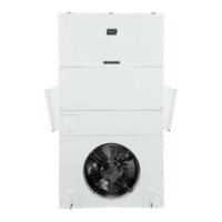
50). Earlier versions of this sensor were installed so
that the sensor wires entered through the top of the
back of the sensor (see Figure 51). The orientation
of the sensor affects the position of the DP1/DP2
jumpers. Depending on how the sensor is installed,
be sure to confirm that the jumpers are in the proper
position for the 0-1 V setting as shown in the figures
below.
This applies to all indoor temperature/humidity
sensors connected to the LC controller. See illustration
mounted inside of sensor cover for further detail on
jumper position.
DP1
DP2
DP1
DP2
Jumper
FIGURE 50
Current Sensor Orientation
(Shielded Cable Wires Enter from Bottom)
FIGURE 51
Earlier Sensor Orientation
(Shielded Cable Wires Enter from Top)
Jumper
DP1 and DP2 Jumpers
Positioned for 0-1V
(Current Orientation)
DP1 and DP2 Jumpers
Positioned for 0-1V
(Earlier Orientation)