Manual 2100-671C
Page 39 of 59
Pressure Service Ports
High and low pressure service ports are installed on
all wall-mount units so that the system operating
pressures can be observed. Pressures are shown in
Tables 12, 13 and 14.
This unit employs high-flow Coremax valves instead of
the typical Schrader type valves.
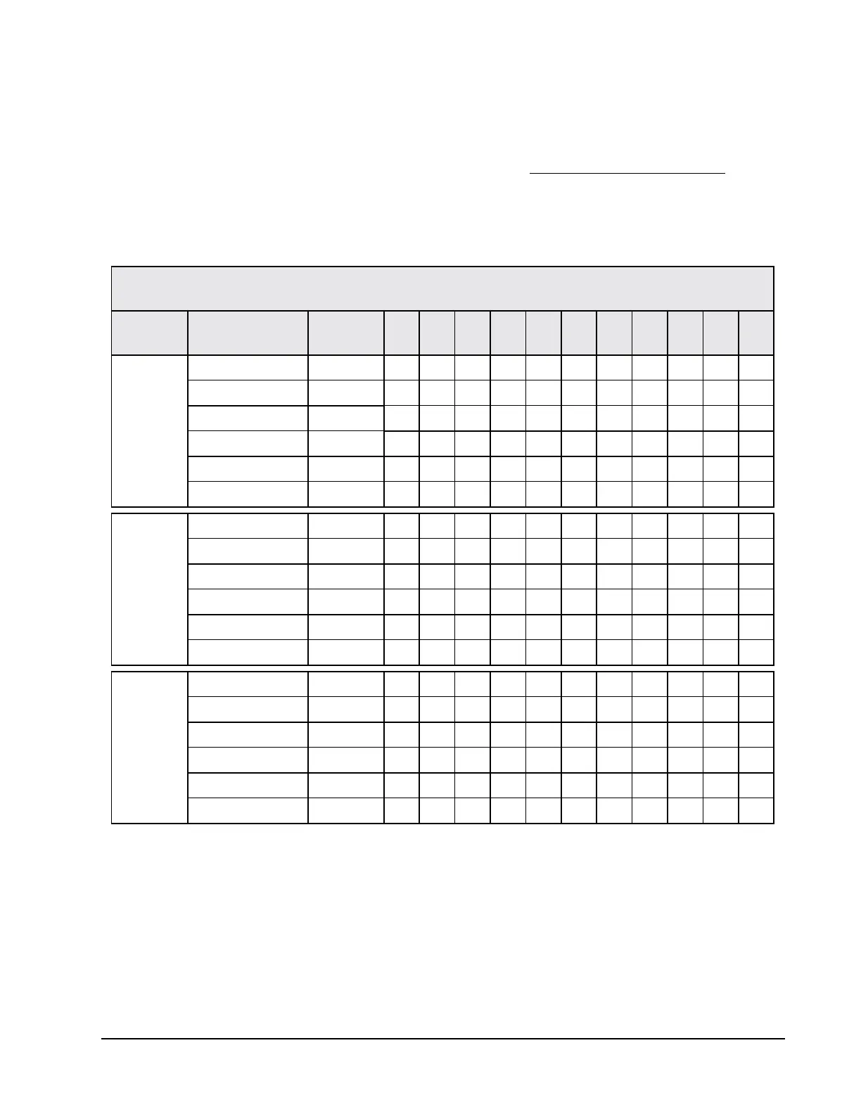
TABLE 12
W090A* Cooling Pressures
Low side pressure ± 4 PSIG
High side pressure ± 10 PSIG
1
Stage 3 is circuit 1 fully loaded and circuit 2 on.
2
Stage 2 is circuit 1 unloaded and circuit 2 on.
3
Stage 1 is circuit 1 unloaded and circuit 2 off.
Tables are based upon rated CFM (airflow) across the evaporator coil. If there is any doubt as to correct operating charge
being in the system, the charge should be removed and system evacuated and recharged to serial plate charge weight.
NOTE: Pressure table based on high speed condenser fan operation. If condensing pressures appear elevated, check
condenser fan wiring. See “Condenser Fan Operation” on page 23.
Cooling Air Temperature Entering Outdoor Coil °F
Model Return Air Temp Pressure 75 80 85 90 95 100 105 110 115 120 125
W090A*
Stage 3
1
75° DB Low Side 135 135 135 136 136 137 137 138 140 142 144
62° WB High Side 389 379 375 375 381 391 407 427 452 483 518
80° DB Low Side 144 144 144 145 145 146 147 148 150 152 154
67° WB High Side 399 389 385 385 391 401 417 438 464 495 531
85° DB Low Side 149 149 149 150 150 151 152 153 155 157 159
72° WB High Side 413 403 398 398 405 415 432 453 480 512 550
W090A*
Stage 2
2
75° DB Low Side 137 140 142 144 146 149 151 152 154 155 157
62° WB High Side 367 356 350 349 354 364 378 399 424 454 489
80° DB Low Side 147 150 152 154 156 159 161 163 165 166 168
67° WB High Side 376 365 359 358 363 373 388 409 435 466 502
85° DB Low Side 152 155 157 159 161 165 167 169 171 172 174
72° WB High Side 389 378 372 371 376 386 402 423 450 482 520
W090A*
Stage 1
3
75° DB Low Side 139 138 138 138 139 140 141 142 144 146 149
62° WB High Side 389 382 378 378 382 390 402 417 437 459 487
80° DB Low Side 149 148 148 148 149 150 151 152 154 156 159
67° WB High Side 399 392 388 388 392 400 412 428 448 471 499
85° DB Low Side 154 153 153 153 154 155 156 157 159 161 165
72° WB High Side 413 406 402 402 406 414 426 443 464 487 516
WARNING! Do NOT use a Schrader valve core removal
tool with these valves. Use of such a tool could result
in eye injuries or refrigerant burns!
To change a Coremax valve without first removing the
refrigerant, a special tool is required which can be
obtained at www.fastestinc.com/en/SCCA07H. See the
replacement parts manual for replacement core part
numbers.