Manual 2100-705B
Page 15 of 43
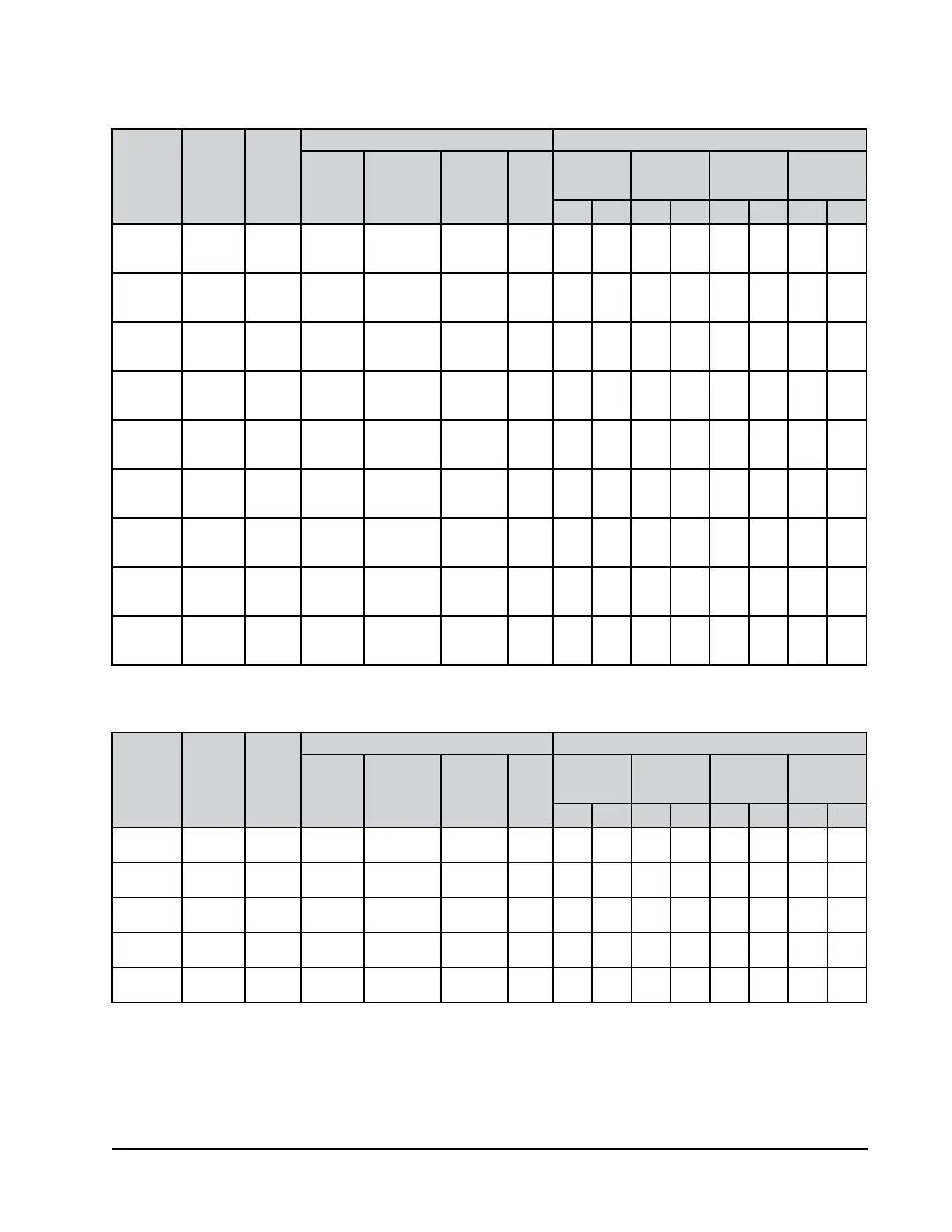
Maximum size of the time delay fuse or circuit breaker for protection of field wiring conductors.
Based on 75°C copper wire. All wiring must conform to the National Electrical Code and all local codes.
These “Minimum Circuit Ampacity” values are to be used for sizing the field power conductors. Refer to the National Electrical code (latest version), Article 310
for power conductor sizing.
CAUTION: When more than one field power circuit is run through one conduit, the conductors must be derated. Pay special attention to Note 8 of Table 310
regarding Ampacity Adjustment Factors when more than three current carrying conductors are in a raceway.
IMPORTANT: While this electrical data is presented as a guide, it is important to electrically connect properly sized fuses and conductor wires in accordance
with the National Electrical Code and all local codes.
Model
Rated Volts
& Phase
No. Field
Power
Circuits
Single Circuit Dual Circuit
Minimum
Circuit
Ampacity
Maximum
External Fuse
or Ckt. Brkr.
Field Power
Wire Size
Ground
Wire
Minimum
Circuit
Ampacity
Maximum
External Fuse or
Ckt. Breaker
Field Power
Wire Size
Ground
Wire Size
Ckt. A Ckt. B Ckt. A Ckt. B Ckt. A Ckt. B Ckt. A Ckt. B
W090APB0Z
B09
B18
230/208-
60-3
1
1
1
46
46
59
60
60
60
6
6
6
10
10
10
W090APC0Z
C09
C18
460-60-3
1
1
1
26
26
26
40
40
40
8
8
8
10
10
10
W120APB0Z
B09
B18
230/208-
60-3
1 or 2
1 or 2
1 or 2
56
56
59
70
70
70
6
6
6
8
8
8
32
32
32
25
28
28
40
40
40
40
40
40
8
8
8
8
8
8
10
10
10
10
10
10
W120APC0Z
C09
C18
460-60-3
1
1
1
27
27
30
40
40
40
8
8
8
10
10
10
W120APE0Z
E09
E18
220/200-
50-3
1
1
1
55
55
59
70
70
70
6
6
6
8
8
8
W120APV0Z
V07
V14
415-50-3
1
1
1
27
27
30
40
40
40
8
8
8
10
10
10
W120APQ0Z
Q09
Q18
575-60-3
1
1
1
24
24
27
35
35
35
8
8
8
10
10
10
W150APB0Z
B09
B18
230/208-
60-3
1 or 2
1 or 2
1 or 2
67
67
67
80
80
80
4
4
4
8
8
8
39
39
39
29
29
29
50
50
50
40
40
40
8
8
8
8
8
8
10
10
10
10
10
10
W150APC0Z
C09
C18
460-60-3
1
1
1
32
32
32
40
40
40
8
8
8
10
10
10
TABLE 2A
Electrical Specifications – W***AP Series
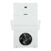
Model
Rated Volts
& Phase
No. Field
Power
Circuits
Single Circuit Dual Circuit
Minimum
Circuit
Ampacity
Maximum
External Fuse
or Ckt. Brkr.
Field Power
Wire Size
Ground
Wire
Minimum
Circuit
Ampacity
Maximum
External Fuse or
Ckt. Breaker
Field Power
Wire Size
Ground
Wire Size
Ckt. A Ckt. B Ckt. A Ckt. B Ckt. A Ckt. B Ckt. A Ckt. B
W120AEB09
B18
230/208-
60-3
1 or 2
1 or 2
83
110
90
120
4
2
8
6
59
59
25
55
60
60
30
30
6
6
10
6
10
10
10
10
W120AEC09
C18
460-60-3
1
1
40
54
50
60
8
6
10
10
W120AEE07
E14
220/200-
50-3
1 or 2
1 or 2
82
110
90
120
4
2
8
6
59
59
24
46
60
60
40
60
6
6
8
8
10
10
10
10
W120AEV07
V14
415-50-3
1
1
40
53
50
60
8
6
10
10
W120AEQ09
Q18
575-60-3
1
1
32
43
40
45
8
8
10
10
TABLE 2B
Electrical Specifications – W***AE Series