Manual 2100-705B
Page 28 of 43
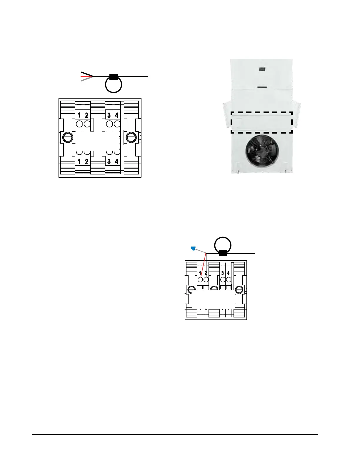
FIGURE 25
Communication Wiring: Termination at Additional Wall-Mount Units
1. Route the cable from the first wall-mount unit to the
terminal block of the second wall-mount unit. If this is
the last unit to be connected, make a small service loop
and attach EMI filter as shown.
2. Connect the wires matching the terminal
designations (+/-) on the Field Wiring label
above the terminal block. Cap the loose
drain with a wire nut or electrical tape.
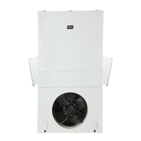
3. Continue daisy chaining units by connecting
"+" to "+", "-" to "-" and wire nutting drain
together until last unit which is capped with
a wire nut. Attach EMI filter as shown above
at last unit. Up to 14 wall-mount units can
be connected and controlled by one LC6000
controller.
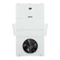
Wall-Mount Unit 2
From Wall-Mount
Unit 1
Unit 2 – 14
Terminal Block
From Wall-Mount
Unit 1
––
++
Unit 2 – 14
Terminal Block
NOTE: Terminals #3 and #4 are dry contacts to be used for the unit disable option.
WARNING: Do not apply voltage to daisy chain connection terminals #1 or #2 or terminals #3 or #4. If 24V or any voltage
is applied to these terminals or to the daisy chain connection, board damage may occur.