BCS36x8
ex
Series Connection example
Type 17-A1S4-*HP* and B7-A2S4-****
Page 56 of 78
Subject to technical changes.
05/2020
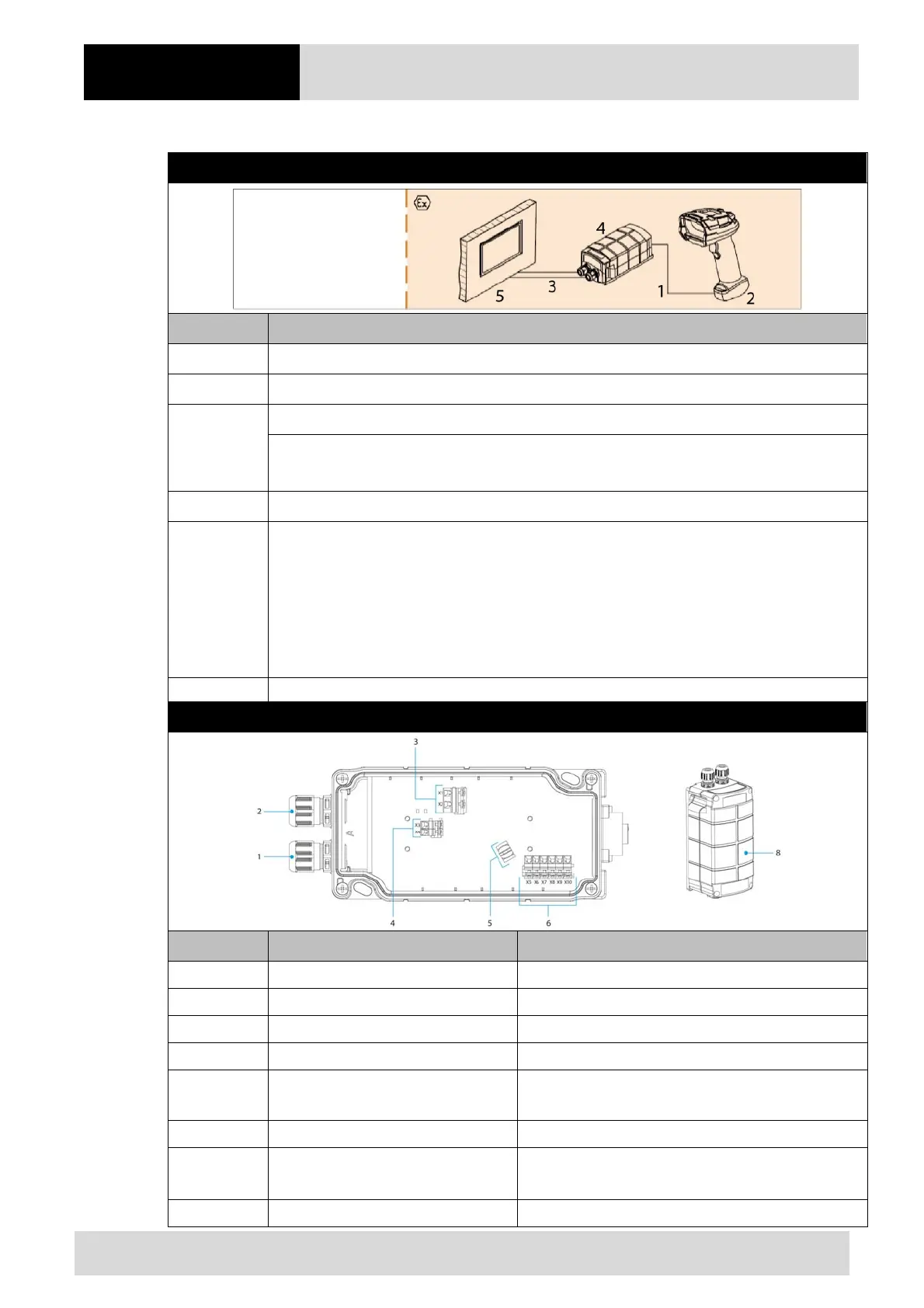
12.1.2 Connection
Diagram
Pos. Description
1 BCS 3608
ex
connection cable
2 BCS 3608
ex
hand-held scanner
3
USB data cable from Ex-HMI to supply module Ex i (max. 5m)
Power supply (100 to 240 V
AC
±10% / 50/60 Hz or 24 V
DC
±10% 0.4A)
Note: NEC/CEC version only with 24V
DC
.
4 Supply module Ex i for hand-held scanners
5
Ex-HMI device
Note: The Ex-HMI device can be replaced by any other Ex device with serial interface.
It is important that the Ex-relevant data must be compatible with the BARTEC
components. See BARTEC User Manual Chapter: "Ex-relevant values when connected
to power supply module or other systems".
Supply module Ex i
Pos. Description Function
1 Cable gland Feed data cable to terminals
2 Cable gland Feed power cord to terminals
3 Terminals X1 to X2 Connect 100 to 240 V
AC
power supply
4 Terminals X3 to X4 Connect 24 V
DC
power supply
5 Shield clamp for ferrite core
The ferrite core is only needed when using the USB-
SPP interface.
6 Terminals X5 to X10 Connect USB data line
7
7-pole round plug
N/A in the Bluetooth version
Plug for wired hand-held scanner
8 Cover Protect / seal terminal connection chamber
 Loading...
