BCS36x8
ex
Series Connection example
Type 17-A1S4-*HP* and B7-A2S4-****
Page 76 of 78
Subject to technical changes.
05/2020
15.1.2 Connection
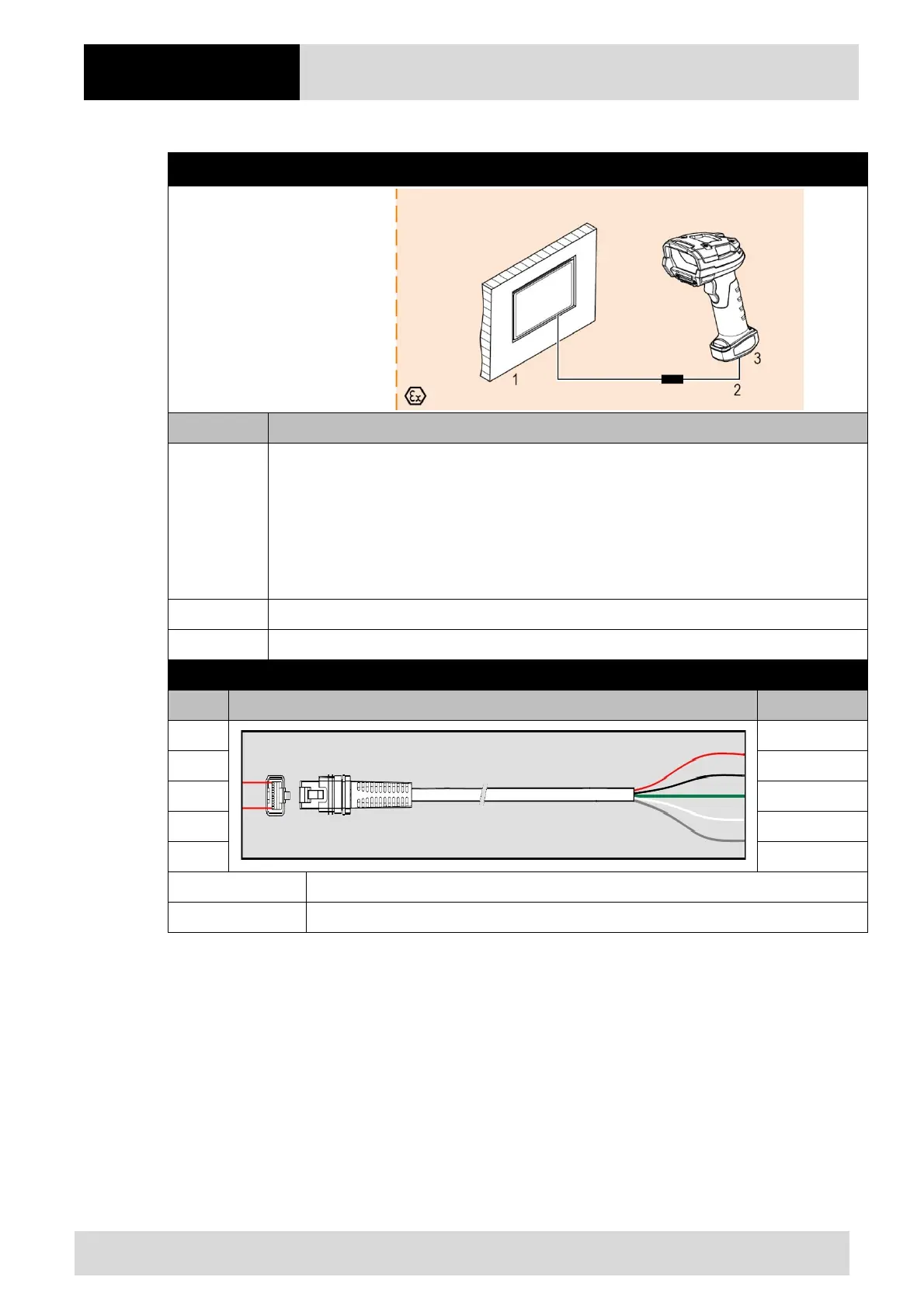
Diagram
Pos. Description
1
Ex-HMI device
Note: The Ex-HMI device can be replaced by any other Ex device with serial interface.
Functional requirement: USB interface must supply 5V
DC
/500 mA on the output side.
It is important that the Ex-relevant data must be compatible with the BARTEC
components. See BARTEC User Manual Chapter: "Ex-relevant values when connected
to power supply module or other systems".
2 HMI limiting cable (B7-A2Z0-0041 or B7-A2Z0-0054)
3 BCS 3608
ex
hand-held scanner
Wiring of HMI limiting cable – USB
RJ-50 Cable diagram Description
Red = V+
PIN 1 Black = GND
PIN 10 Green = D-
White = D+
Grey = Shield
B7-A2Z0-0041 HMI limiting cable, USB; 1.9m; plain
B7-A2Z0-0054 HMI limiting cable, USB; 4.5m; plain
 Loading...
