BCS36x8
ex
Series Connection example
Type 17-A1S4-*HP* and B7-A2S4-****
Subject to technical changes.
05/2020
Page 9 of 78
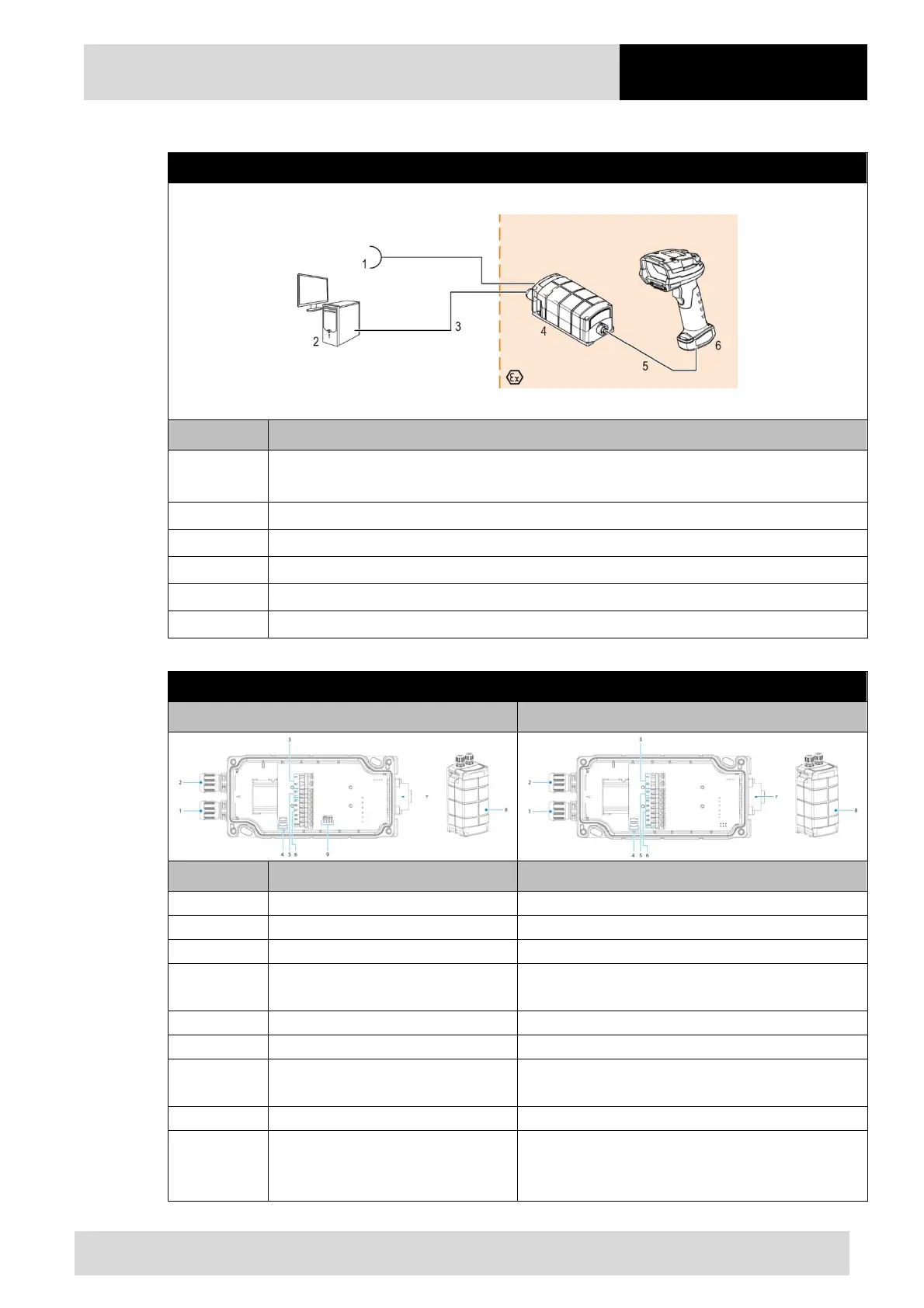
4.1.2 Connection
Diagram
Pos. Description
1
Power supply (100 to 240 V
AC
±10% / 50/60 Hz or 24 V
DC
±10% 0.4A)
Note: NEC/CEC version only with 24V
DC
.
2 Host PC
3 RS232 data cable from host PC to universal supply module (max. 15m)
4 Universal supply module for hand-held scanners
5 BCS 3608
ex
connection cable
6 BCS 3608
ex
hand-held scanner
Universal supply module
1
st
generation with DIP switch 2
nd
generation without DIP switch
Pos. Description Function
1 Cable gland Feed data cable to terminals
2 Cable gland Feed power cord to terminals
3 Terminals X1 to X2 Connect 100 to 240 V
C
power supply
4 Shield clamp for ferrite core
The ferrite core is only needed when using the USB-
SPP interface.
5 Terminals X3 to X4 Connect 24 V
DC
power supply
6 Terminals X5 to X9 Connect RS232 data line
7
7-pole round plug
N/A in the Bluetooth version
Plug for wired hand-held scanner
8 Cover Protect / seal terminal connection chamber
9 DIP switch
Select/set used interface:
1st generation: setup via DIP switches
2nd generation: setup via barcodes
 Loading...
