21
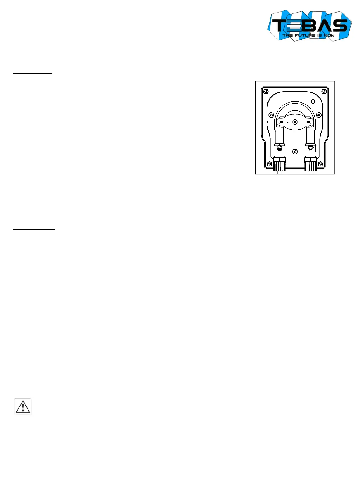
Suction Line
(also see drawing)
1. Unscrew the fixing nut of the connector located on the bottom left side of the pump
head and marked in the figure with an incoming arrow.
2. Cut the transparent PVC Crystal tube.
3. Insert the fixing nut and the tube-wrench on the tube.
4. Mount the tube on the conic tube-holder of the suction connector, pushing it until it
reaches the stop collar.
5. Fix the tube by screwing the fixing nut onto the suction connector of the pump head.
6. Locate the PVC Crystal tube inside the tank and/or the suction lance.
7. Unscrew the fixing nut of the foot filter.
8. Cut the transparent PVC Crystal tube.
9. Insert the fixing nut and the tube-wrench on the tube.
10. Mount the tube on the conic tube-holder of the foot filter connector, pushing it until it
reaches the stop collar.
11. Fix the tube by screwing the fixing nut onto the connector of the foot filter.
12. Screw the foot filter onto the suction lance (if used) and/or locate it in its working
place.
Notes:
• The foot filter must be located at a minimum distance of 5 cm from the tank bottom.
• If a dense product is dosed, it is recommended to remove the small inside filter from the foot valve, in order to facilitate
the suction.
Injection Line
(also see drawing above)
1. Unscrew the fixing nut of the connector located on the bottom right side of the pump head and marked in the figure with
an outgoing arrow.
2. Cut the white, semi-rigid polyethylene tube.
3. Insert the fixing nut and the tube-wrench on the tube.
4. Mount the tube on the conic tube-holder of the suction connector, pushing it until it reaches the stop collar.
5. Fix the tube by screwing the fixing nut onto the head connector of the pump head.
6. Place the injection tube avoiding as much as possible the curves and ensuring that the pulses do not make the tube rub
against rigid bodies.
7. Perform electrical connections (see related section in the manual) and power the pump.
8. At the injection point on the pipeline, mount a ½” GAS connection, internally threaded (not supplied.
9. Wrap PTFE tape to the thread and tighten the injection valve to the fitting.
10. Unscrew the pipe-wrench nut of the injection valve fitting.
11. Cut the white, semi-rigid, PE tube.
12. Insert the pipe-wrench on the PE tube.
13. Mount the tube on the conic hose of the injection valve, pushing it until it reaches the stop collar.
14. Screw the pipe-wrench nut onto the valve fitting.
Note: The injection valve also works as non-return valve: do not disassemble it internally.
ELECTRICAL CONNECTIONS
The Tebas-Economic EFka265 unit is supplied already wired internally and complete with power cable (with plug upon
request). This is the only electrical connection to be performed by the customer.
Standard power supply: 230 V∼, 50 Hz, monophasic.
Carefully follow all the rules of electrical safety.
Before starting the unit, check that all electrical and plumbing connections have been properly executed.
The measure inputs from pH and redox electrodes are available on BNC connectors, while inputs for level sensors (one for
each pump) and flow sensor are available on special connectors that allow an extremely fast and easy connection even for
unskilled personnel.
Note: the pH and redox inputs should never be left open; if an input is not used, you need to short-circuit it.