27
Notes
If the system does not automatically recognize the buffers or the “Calibration Impossible” error occurs, it can be due to:
a) buffer solution contaminated or expired
b) electrode faulty or dead
c) connection cable or connector damaged
If you try to calibrate the offset at a pH value too different from 7.00, the calibration is automatically ignored. Similarly if
you try to calibrate the gain with a buffer solution at a pH too close to neutrality, the procedure will fail.
During normal operation, it is possible to view the offset (pressing ⇓) and gain (pressing ⇑) values, to check the
electrode status. The ideal values are an offset close to zero and a gain close to 1.000. When these values are close to
the max / min limits (offset: -1.00pH ... +1.00pH; gain: 0.750 ... 1.500), the electrode is contaminated or dead.
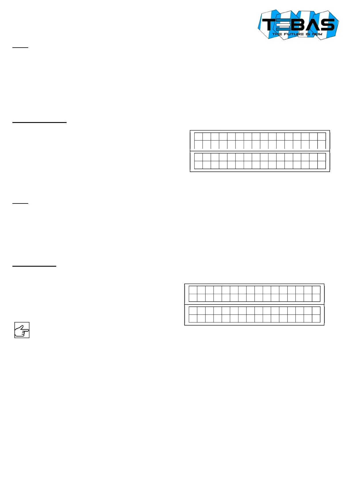
Redox Calibration
1) Rinse the electrode with distilled water, then immerse it in the calibration solution (e.g. 220 mV).
2) Press the CAL key to enter the menu mode and use the ⇑ / ⇓
keys to select the option “IN2 CALIBRATION”.
3) Press CAL again to confirm.
4) Press ⇓ to select the OFFSET calibration and confirm by
pressing CAL.
5) The system automatically recognizes and displays the solution
value (220 mV).
6) If necessary, use the ⇑ / ⇓ keys to adjust the calibration value.
7) Press CAL to confirm the calibration, or ESC to quit the procedure and keep the previous calibration.
Notes
If the system does not automatically recognize the buffers or the “Calibration Impossible” error occurs, it can be due to:
a) calibration solution contaminated or expired
b) electrode faulty or dead
c) connection cable or connector damaged
During normal operation, it is possible to view the offset value by pressing ⇓, to check the electrode status. The ideal
offset value is close to zero. When this value is close to the max / min limits (-100mV ... +100mV), the electrode is
contaminated or dead.
Manual Mode
At any time you can force a manual working mode, useful for a temporary use of the system.
If a password has been set (see parameter P16), the system will require it to enable the access to this feature.
1) Press the CAL key to enter the menu mode and use the ⇑ /
⇓ keys to select the option “MANUAL FUNC.1” (or
“MANUAL FUNC.2”).
2) Press CAL again to confirm.
3) Similarly proceed for pump 2.
4) Press ESC at any time to exit the manual mode.
Warning! In manual mode only one pump at a time can be activated.
CONTROL EXAMPLES
Typical application in swimming pool control: acidification when pH exceeds the pH value of 7.30.
Refer to the “List of configuration parameters” and set:
- P01 ON/OFF working mode for pump 1
- P02 set-point 7.30 pH
- P04 dosage direction “ACIDIFICATION”
- P11 alarm pump 1 = 60 minutes
Typical application in swimming pool control: chlorination when redox potential falls below 680 mV. Refer to the “List of
configuration parameters” and set:
- P06 PROPORTIONAL working mode (recommended for an easier stabilisation)
- P07 set-point 680 mV
- P09 dosage direction “CHLORINATION”
- P10 if the quantity of the product to be injected is not known, it is recommended to start with a time base of 60
seconds (default), and if the chlorination process would last too long, decrease the time base gradually until a
conditioning time of approx. 30-45 minutes
- P12 alarm pump 2 = 60 minutes
I N
2
C
A
L
I B
R
A
T
. R
X
C
A
L
>
Y
E
S
E
S
C
>
N
O
I N
2
C
A
L
I B
R
A
T
. R
X
⇓
O
F
F
S
E
T
M
A
N
U
A
L
F
U
N
C
. P
1
C
A
L
>
Y
E
S
E
S
C
>
N
O
M
A
N
U
A
L
P
U
M P
1
O
F
F