22
Level Control (optional)
The system is supplied already configured for disabling the dosage in case of low level in the tank. The
level control is made through a specific float sensor (optional, see “Accessories and spare parts”), to be
connected to pins 3 and 4 of the LEV connector (see Figure). When the product level in the tank falls
below the level sensor, the unit stops dosing and the fault is shown on the display. The alarm condition is
generated with a delay of a few seconds compared to the detection of low level, to avoid errors due to
extreme situation (such as water surface). Two inputs for level sensor are available, one for each
pump/tank.
Flow Control (optional)
The system is supplied already configured for disabling the dosage in case of lack of water flow. The
control is made through a SPDT contact to be connected to pins 3 and of the FLOW connector (see
Figure). A specific flow sensor is also available (optional, see “Accessories and spare parts”).
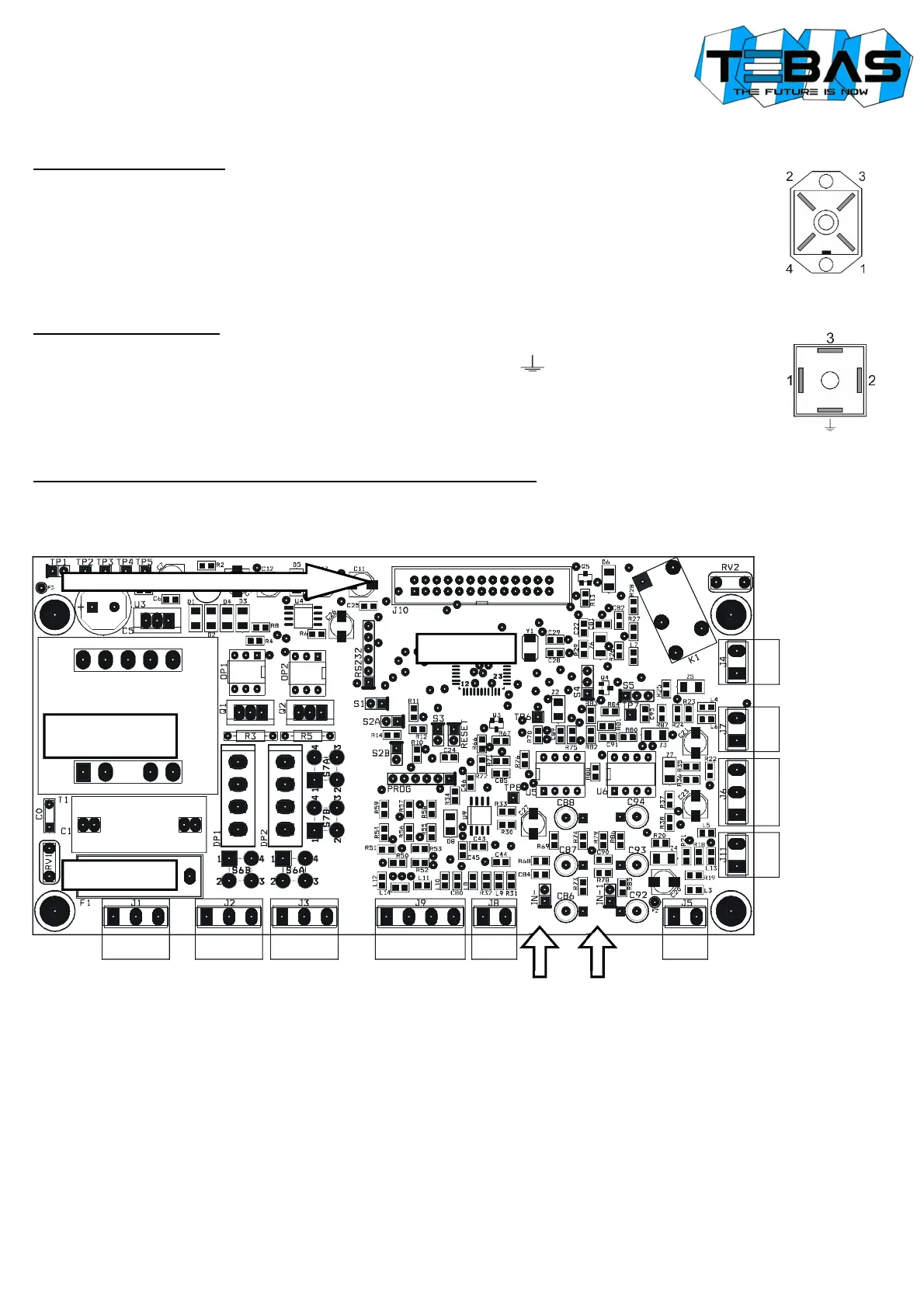
INTERNAL CONNECTIONS (for technical personnel only)
The unit is provided pre-wired internally, and all connections of normal use (power supply, measurement sensors and level
sensors) are available externally via cable or connector.
However, if you need to operate on the electronic boards or replace blown fuses, refer to the diagram below.
Notes:
• The possible reversal of the connections line / neutral of the power supply does not affect the normal operation.
• If the level and flow inputs are not used, leave them open (not connected).
START-UP
At start-up the microcontroller displays for a couple of seconds information about the firmware (type/version), then shows the
two measures flashing for all the start-up delay time (if set) and then starts operating accordingly with the configured working
mode.
Reserved
Transformer
Fuse F1A
Pump 1
Y/G N L
Power Supply
µProcessor
PT100
Br Bk Bl
Flow
+ -
Level 1
Connector for front board flat cable
Pump 2
IN pH
IN RX
Reserved
OUT
Alarm
+ -
Level 2