RoboClaw Series
Brushed DC Motor Controllers
RoboClaw Series User Manual
24
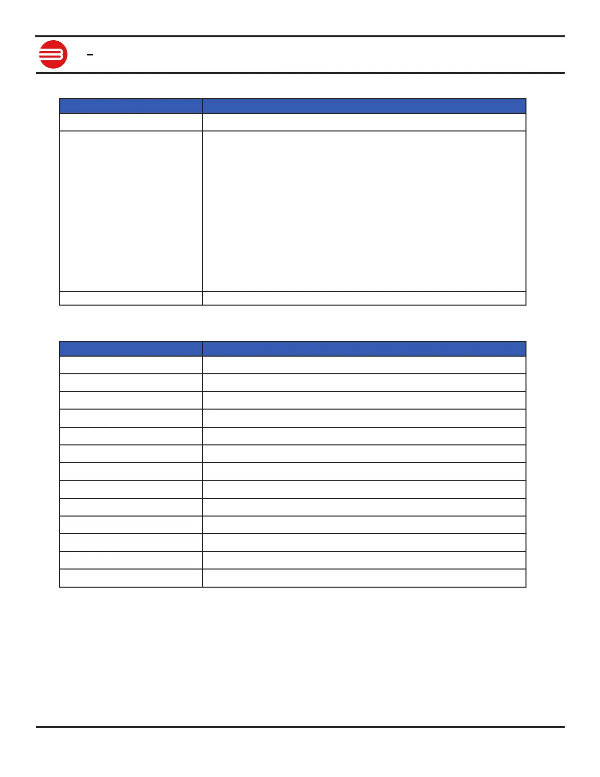
(2) Graph Channels
Function Description
Scale Sets vertical scale to t the range of the specied Channel.
Channels Select data to display on the channel. The channel is graphed in the color
shown. Channel options:
• M1 or M2 Setpoint - User input for channel
• M1 or M2 PWM - Motor PWM output
• M1 or M2 Velocity - Motors Encoder Velocity
• M1 or M2 Position - Motors Encoder Position
• M1 or M2 Current - Motor running current
• Temperature
• Main Battery Voltage
• Logic Battery Voltage
Clear Clears channels graphed line.
(3) Position Settings
Function Description
Velocity P Proportional setting for velocity PID.
Velocity I Integral setting for velocity PID.
Velocity D Dierential setting for velocity PID.
QPPS Maximum speed of motor using encoder counts per second.
L MCP only. Motor Inductance in Henries.
R MCP only. Motor resistance in Ohms.
Position P Proportional setting for position PID.
Position I Integral setting for position PID.
Position D Dierential setting for position PID.
Max I Maximum integral windup limit.
Deadzone Zero position deadzone. Increases the "stopped" range.
Min Pos Minimum encoder position.
Max Pos Maximum encoder position.