RoboClaw Series
Brushed DC Motor Controllers
RoboClaw Series User Manual
62
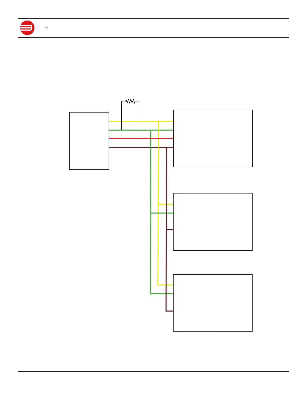
Multi-Unit Packet Serial Wiring
In packet serial mode up to eight Roboclaw units can be controlled from a single serial port.
The wiring diagram below illustrates how this is done. Each Roboclaw must have multi-unit
mode enabled and have a unique packet serial address set. This can be congured using Motion
Studio. Wire the S1 and S2 pins directly to the MCU TX and RX pins. Install a pull-up resistor
(R1) on the MCU RX pin. A 1K to 4.7K resistor value is recommended. For model specic pinout
information please refer to the data sheet for the model being used.
S1 Signal
S2 Signal
5VDC
GROUND
RoboClaw 2
S1 Signal
S2 Signal
5VDC
GROUND
RoboClaw 3
S1 Signal
S2 Signal
5VDC
GROUND
RoboClaw 1
UART TX
UART RX
5VDC
GROUND
MCU
R1