RoboClaw Series
Brushed DC Motor Controllers
RoboClaw Series User Manual
54
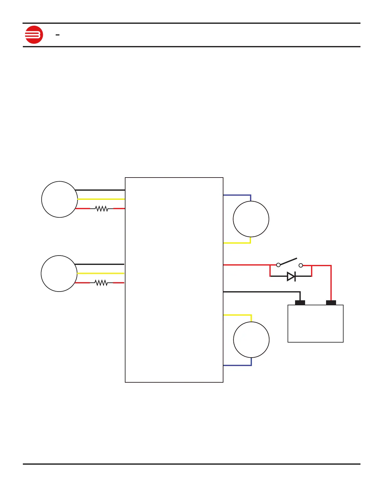
Analog Wiring Example
RoboClaw uses a high speed 12 bit analog converter. Its range is 0 to 2V. The analog pins
are protected and 5V tolerant. The potentiometer range will be limited if 5V is utilized as the
reference voltage. A simple resistor divider circuit can be used to reduce the on board 5V to 2V
for use with a potentiometer(POT). See the below schematic. The POT acts as one half of the
resistor divider. If using a 5k potentiometer R1 / R2 = 7.5k, If using a 10k potentiometer R1 / R2
= 15k and if using a 20k potentiometer R1 / R2 = 30k.
Set mode 3 with option 1 if using autocalibration. Center the potentiometers before applying
power. The S1 potentiometer will control the motor 1 direction and speed. The S2 potentiometer
will control the motor 2 direction and speed.
For model specic pinout information please refer to the data sheet for the model being used.
S2 Signal
5VDC
GROUND
Pot 2
S1 Signal
5VDC
GROUND
Pot 1
M1A
M1B
M2B
M2A
Negative -
Positive +
+
-
Battery
RoboClaw
Motor 1
Motor 2
R2
R1
D1
SW1