RoboClaw Series
Brushed DC Motor Controllers
RoboClaw Series User Manual
46
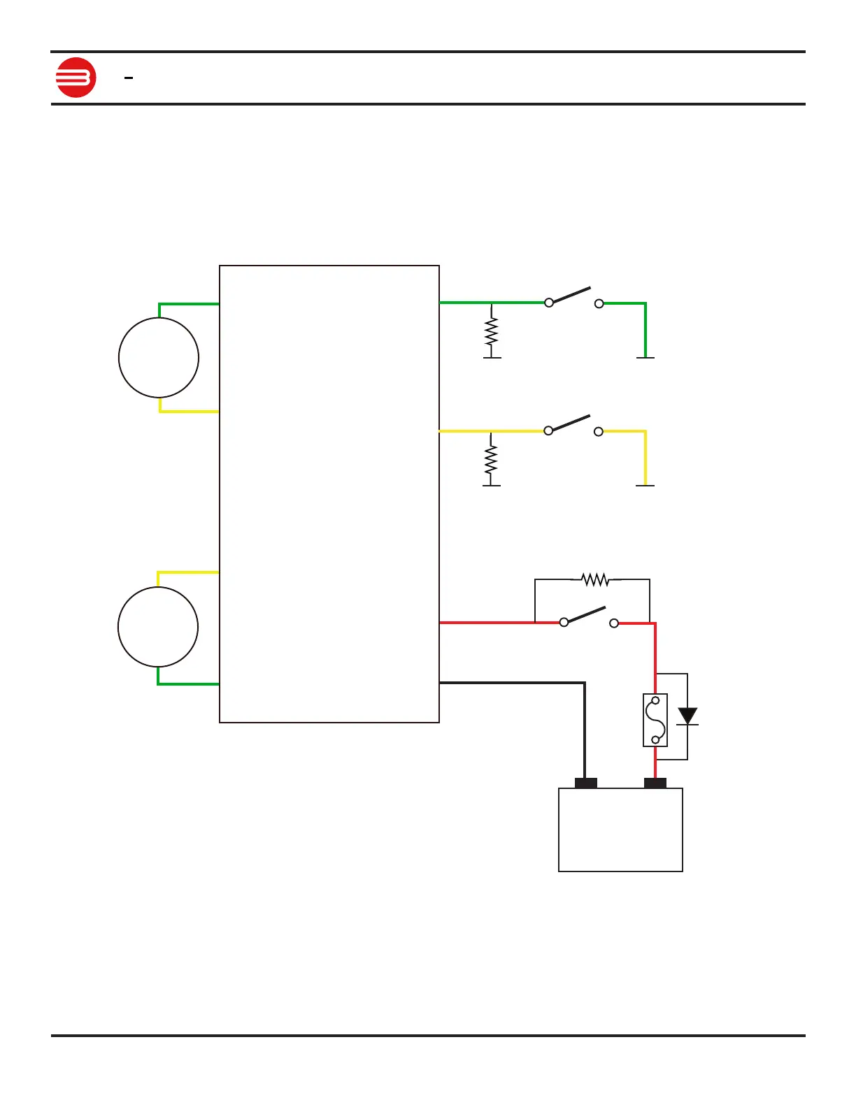
Limit / Home / E-Stop Wiring
S4 controls motor channel 1 and S5 controls motor channel 2. A pull-up resistor to 5VDC or
3.3VDC should be used if wire lengths exceed 6” (150mm). The circuit below shows a NO
(normally open) style switch. Connect the NO to S4 or S5 and the COM end to a power ground
shared with RoboClaw.
For model specic pinout information please refer to the data sheet for the model being used.
Motor 1
Motor 2
M1A
M1B
M2B
M2A
ROBOCLAW
+
-
Battery
R1
F1
D1
B-
B+
SW1
S5
5+
R3
SW3
GND
S4
5+
R2
SW2
GND