9287500991 Rev K DECS-100 General Information 1-1
SECTION 1 • GENERAL INFORMATION
INTRODUCTION
The Basler Digital Excitation Control System (DECS-100) is an electronic, solid-state, microprocessor
based control device. The DECS-100 regulates the output voltage of a brushless, ac generator by
controlling the current into the generator exciter field. Input power to the DECS-100 can be from a multi-
pole, high-frequency, permanent magnet generator (PMG) or from the generator output when used as a
conventional, shunt-excited, excitation system.
The DECS-100 is supplied in an epoxy-potted package designed for behind-the-panel mounting. The
DECS-100 is held in place by thread-forming screws that thread into its plastic shell. Front panel
indicators (LEDs) annunciate DECS-100 status and system conditions. DECS-100 connections are made
through quarter-inch, quick-connect terminals on the rear panel. A 9-pin DB-9 type connector on the rear
panel provides communication between the DECS-100 and an IBM compatible PC.
FEATURES
DECS-100 units have the following features and capabilities:
• Four control modes: automatic voltage regulation (AVR), manual or field current regulation (FCR),
power factor (PF) regulation, and reactive power (var) regulation.
• Programmable stability settings.
• Soft start and voltage buildup control with an adjustable ramp in AVR control mode.
• Overexcitation limiting (OEL) and underexcitation limiting (UEL) in AVR, Var, and PF control modes.
• Underfrequency (volts/hertz) regulation.
• Three-phase or single-phase generator voltage (rms) sensing/regulation in AVR mode.
• Single-phase bus voltage (rms) sensing.
• Single-phase generator current sensing for metering and regulation purposes.
• Field current and field voltage sensing.
• One analog input for proportional remote control of the setpoint.
• Five contact sensing inputs for system interface.
• One common output relay for alarm indication and trip functions.
• Three protection functions: field overvoltage, generator overvoltage, and loss of sensing.
• Generator paralleling with reactive droop compensation and reactive differential compensation.
• Rear RS-232 communication port for personal computer communication using BESTCOMS
Windows® based software for fast, user-friendly, setup and control.
MODEL AND STYLE NUMBER
The model number, together with the style number, describe the options included in a specific device, and
appear on a label affixed to the rear panel. Upon receipt of a DECS-100, be sure to check the style
number against the requisition and the packing list to ensure that they agree.
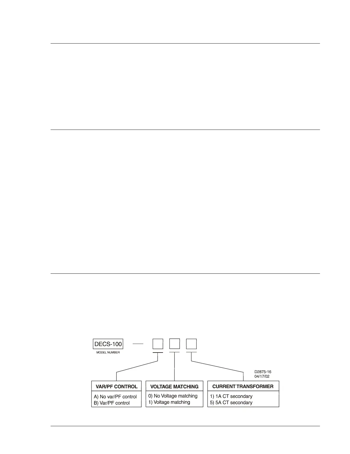
Style Number
DECS-100 electrical characteristics and operational features are defined by a combination of letters and
numbers that make up the style number. The DECS-100 style number chart is shown in Figure 1-1.
Figure 1-1. DECS-100 Style Chart