4-4 DECS-100 Installation 9287500991 Rev K
CONNECTIONS
DECS-100 connections are dependent on the application and excitation scheme. Incorrect wiring may
result in damage to the unit. Check the part number to ensure that you have the correct unit before
connecting and applying power.
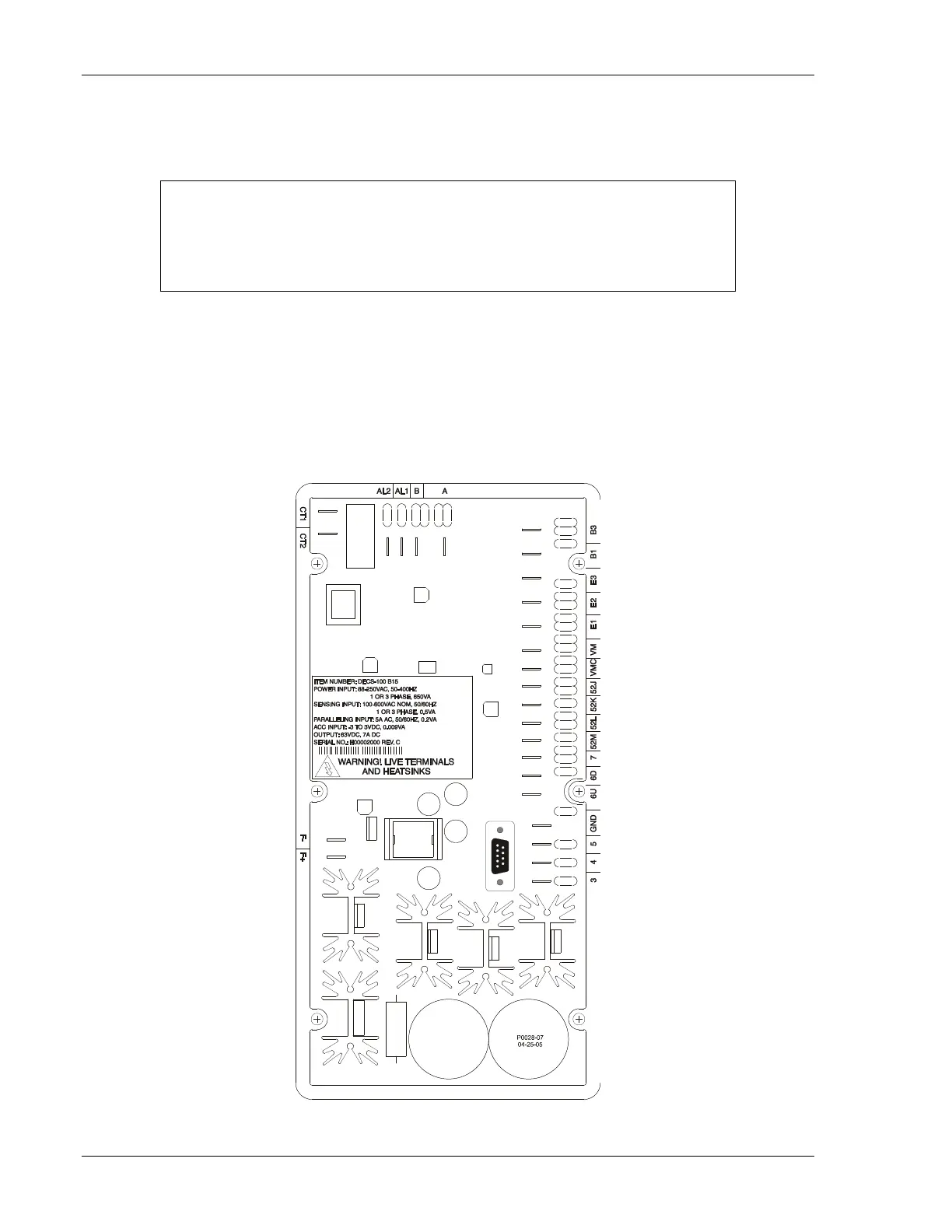
DECS-100 Terminations
DECS-100 units have two types of interface terminals (Figure 4-3). One type is quarter-inch, quick-
connect terminals and the other is a 9-pin DB9 connector. All terminals are located on the rear of the unit.
The quarter-inch, quick-connect terminal labels are located on the rear of the case. Wires performing
common functions, such as voltage sensing leads, should be grouped together. The 9-pin DB-9 type
connector is used for temporary interface with both IBM compatible PCs and hand-held computers.
Figure 4-3 shows the terminal connections located on the rear panel of the DECS-100. Except as noted
above, connections should be made with minimum wire size of 14 AWG.
Figure 4-3. DECS-100 Terminals
Be sure that the DECS-100 is hard-wired to earth ground with no smaller than 12
AWG copper wire attached to the ground terminal on the rear of the unit case.
When the unit is configured in a system with other devices, connect a separate
lead from the ground bus to each DECS-100 unit.