5-4 DECS-100 BESTCOMS Software 9287500991 Rev K
Regulator Sensing Current (A).
This setting field reads and displays the nominal output of the current
transformer (CT) that supplies the DECS-100 with B-phase generator line current. This value (1 or 5)
must be manually entered for units with a firmware version lower than 1.12.01.
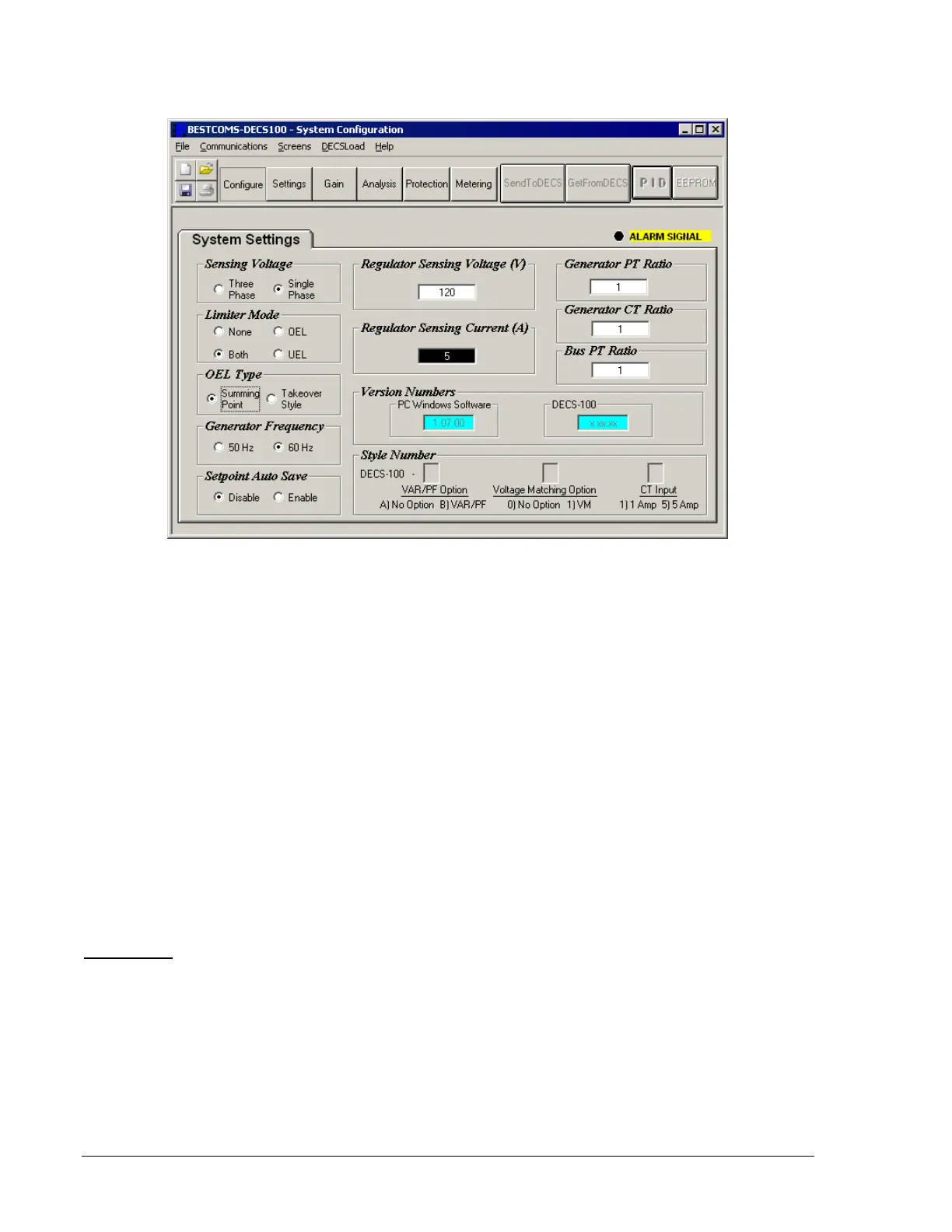
Figure 5-6. System Configuration Screen
Version Numbers.
These two read-only version numbers indicate the BESTCOMS software version and
the DECS-100 embedded software version. Version numbers are displayed only when communication
between the DECS-100 and BESTCOMS is established.
Style Number.
The three, read-only style number fields indicate the electrical characteristics and
operational features of the DECS-100. the style number is displayed only when communication between
the DECS-100 and BESTCOMS is established.
Generator PT Ratio.
The ratio of the generator sensing transformer is entered in this setting field. This
ratio allows the voltage displayed through BESTCOMS to match the actual generator output voltage. A
ratio of 1 to 150 may be entered in increments of 0.01.
Generator CT Ratio.
The ratio of the generator B-phase current transformer is entered in this setting field.
This ratio allows the current displayed by the DECS-100 to match the actual B-phase generator output
current. A ratio of 1 to 3,000 may be entered in increments of 0.1.
Bus PT Ratio.
This setting field is used to enter the bus potential sensing transformer ratio. This ratio
allows the bus voltage to be displayed through BESTCOMS. A ratio of 1 to 150 may be entered in 0.01
increments.
Setting Adjustments
The Setting Adjustments screen consists of two tabs: Setpoint and Startup.
Setpoint Tab
The Setpoint tab settings of the Setting Adjustments screen are shown in Figure 5-7. Each setting of the
Setpoint tab is described in the following paragraphs.
Automatic Voltage Regulator (AVR) - AVR Setpoint (V).
This setting field is used to enter the desired
generator output terminal voltage. The AVR setpoint value range depends on the regulator sensing
voltage and band setting.
Fine Voltage Adjustment - Band Setting (%).
The Band Setting determines the minimum and maximum
adjustment allowed to the AVR Setpoint (as a percentage of the Regulator Sensing Voltage setting (see
Figure 5-8)). Band Setting values are entered as a percentage of the regulator sensing voltage setting
over a range of 0 to 15%in 0.1% increments.