Physical Interface
Basler scout 61
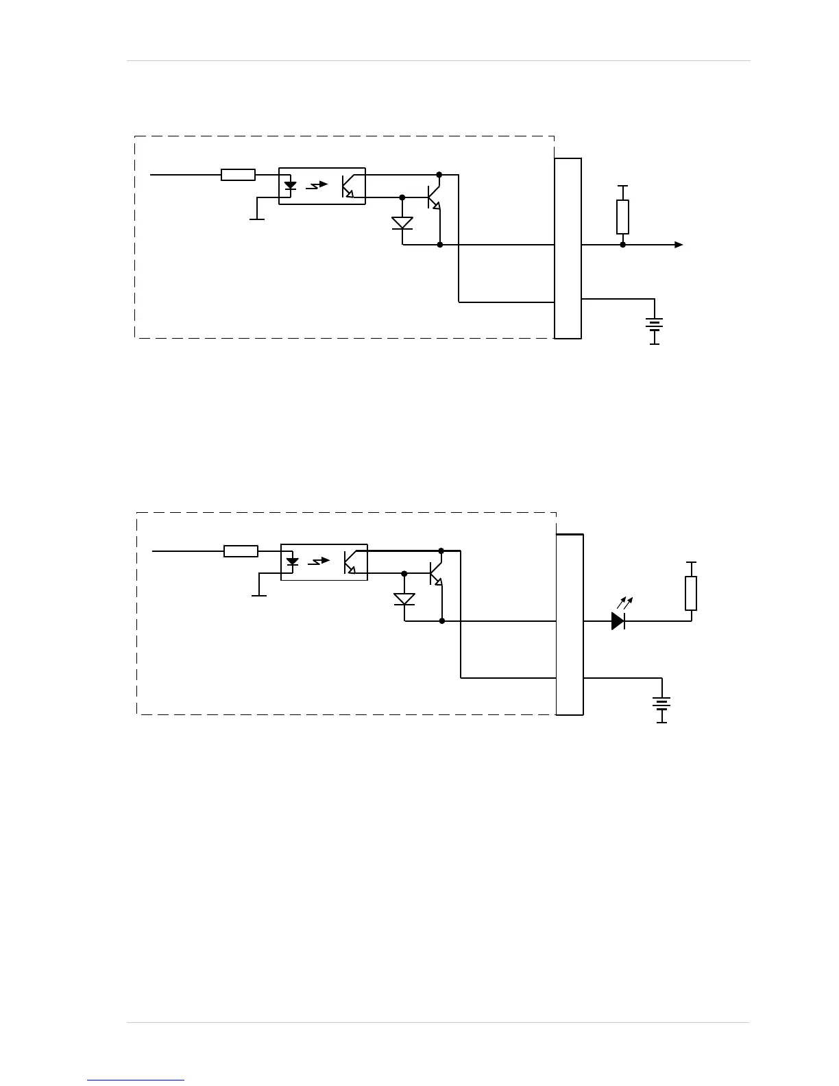
Fig. 36: Typical Voltage Output Circuit
Figure 37 shows a typical circuit you can use to monitor an output line with an LED or an opto-
coupler. In this example, the voltage for the external circuit is +24 VDC. Current in the circuit is
limited by an external resistor. The circuit in Figure 37 is monitoring output line 1.
Fig. 37: Typical LED Output Signal at +24 VDC for the External Circuit (Example)
By default, the camera’s exposure active (ExpAc) signal is assigned to Output Line 1. The exposure
active signal indicates when exposure is taking place.
By default, the camera’s trigger ready (TrigRdy) is assigned to Output Line 2. The trigger ready
signal goes high to indicate the earliest point at which exposure start for the next frame can be
triggered.
The assignment of camera output signals to physical output lines can be changed by the user.