Physical Interface
Basler scout 59
5.7.1.2 Line Schematic
The camera is equipped with two physical input lines designated as Input Line 1 and Input Line 2.
The input lines are accessed via the 12-pin receptacle on the back of the camera.
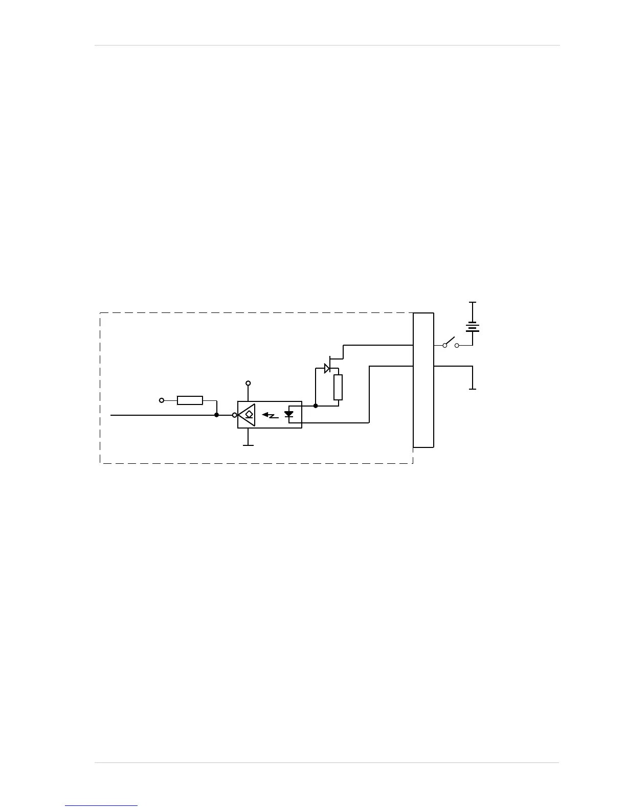
As shown in the I/O line schematic, each input line is opto-isolated. See the previous section for
input voltages and their significances. The absolute maximum input voltage is +30.0 VDC. The
current draw for each input line is between 5 and 15 mA.
Figure 35 shows an example of a typical circuit you can use to input a signal into the camera.
By default, Input Line 1 is assigned to receive an external hardware trigger (ExTrig) signal that can
be used to control the start of image acquisition.
Fig. 35: Typical Input Circuit
For more information on input line pin assignments and pin numbering, see Section 5.2 on page 50.
For more information about how to use an ExTrig signal to control image acquisition, see
Section 7.4.5 on page 90, Section 7.5.3 on page 98, and Section 7.6.3 on page 109.
For more information about configuring the input lines, see Section 6.1 on page 65.