11
2.3 Process-andDataInterface
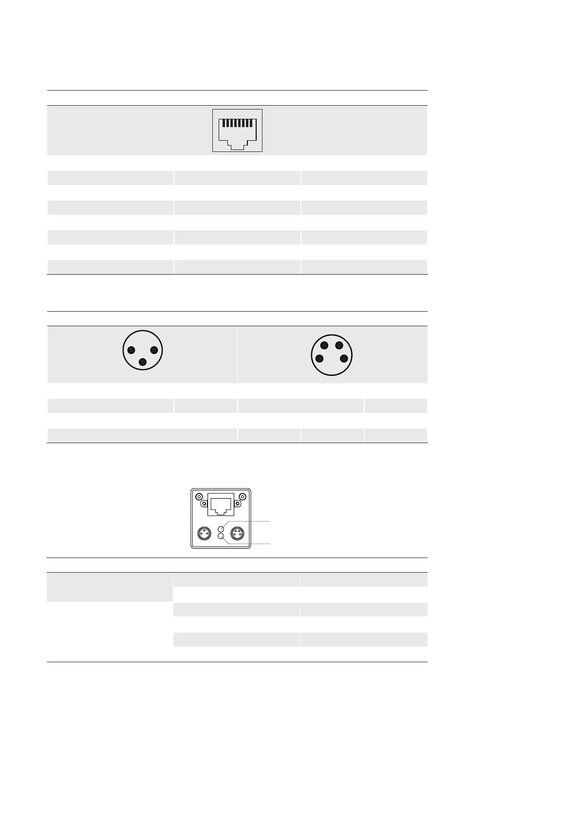
2.3.1 Pin-AssignmentGigabitEthernetInterface
8P8C mod jack
1 (gn/wh) MX1+
2 (gn) MX1-
3 (og/wh) MX2+
4 (bu) MX3+
5 (bu/wh) MX3-
6 (og) MX2-
7 (bn/wh) MX4+
8 (bn) MX4-
2.3.2 Pin-AssignmentPowerSupplyandDigitalIOs
M8/3pins M8/4pins
1 (bn) Power V
CC
1 (bn) TrigIN+
3 (bu) GND 2 (wh) TrigIN-
4 (bk) NC 3 (bu) Flash
out
4 (bk) U
ext
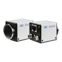
2.3.3 LEDSignaling
1
LED Signal Meaning
1
green Power on
yellow Readout active
2
green Link active
green ash Receiving
yellow Transmitting
yellow / red ash Receiving and Transmitting
◄Figure7
LED positions on Baumer EXG
cameras.