TA202
32 www.baumer.com
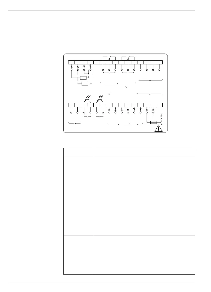
3 Connecting
This chapter first describes terminal assignment of the device, follo-
wed by some connection examples. Chapters 3.1 to 3.5 provide con-
crete remarks and specifications regarding the individual terminals.
The electrical inputs and outputs are configured on two plug-in
screw terminals. The two 15-pole screw-type terminals are coded wi-
thout pole loss.
Terminal assignment
Br.
RU
RI
RxD-
RxD+
TxD-
TxD+
RS422
max. 250 V
terminal - terminal /
- terminal
Limit value
Signal Sensor
supply
Stop
F2
Start
F1 B
F1 A
+24V
0V
Voltage supply
30 29 28 27 26 25 24 23 22 21 20 19 18 17 16
15 14 13 12 11 10 987654321
(-)
(+)
T,R+
T,R-
RS485
GND
RxD
TxD
RS232
Limit value
21
21
Terminal assignment
Terminal Function
1
2
3
4
5
6
7
8
9
10
11
12
13
14
15
Not assigned
Supply voltage
Supply voltage
Sensor supply 0 V
Sensor supply +24 V
Signal F1/A (track A)
Signal F1/B (track B)
Signal F2/start
Signal stop
Limit value 1 (collector)
Limit value 1 (emitter)
Limit value 2 (collector)
Limit value 2 (emitter)
Option RS485 T,R-
Option RS485 T,R+
16-19
20-22
23-25
27
28
29
30
Option RS232 or RS422
Option relay output limit value 1 (P1)
Option relay output limit value 2 (P2)
Option analog output
Option analog output (jumper at U)
Option analog output (I)
Option analog output (U)